Removing the flail screen, Sharpening or replacing the blades, Chipper blades – Craftsman 247.775880 User Manual
Page 15: Service & adjustments
Attention! The text in this document has been recognized automatically. To view the original document, you can use the "Original mode".
SERVICE & ADJUSTMENTS
REMOVING THE FLAIL SCREEN
If the discharge area becomes clogged, remove the
flail screen and clean area as follows.
•
Stop eng I ne, ma ke ce rtai n the chipper
shredder has come to a complete stop and
disconnect spark plug wire from the spark plug
before unclogging the chute.
•
Remove the two hand knobs on each side of
the discharge chute (also called the chute
deflector).
•
Lift the discharge chute up, and keep it out of
the way.
•
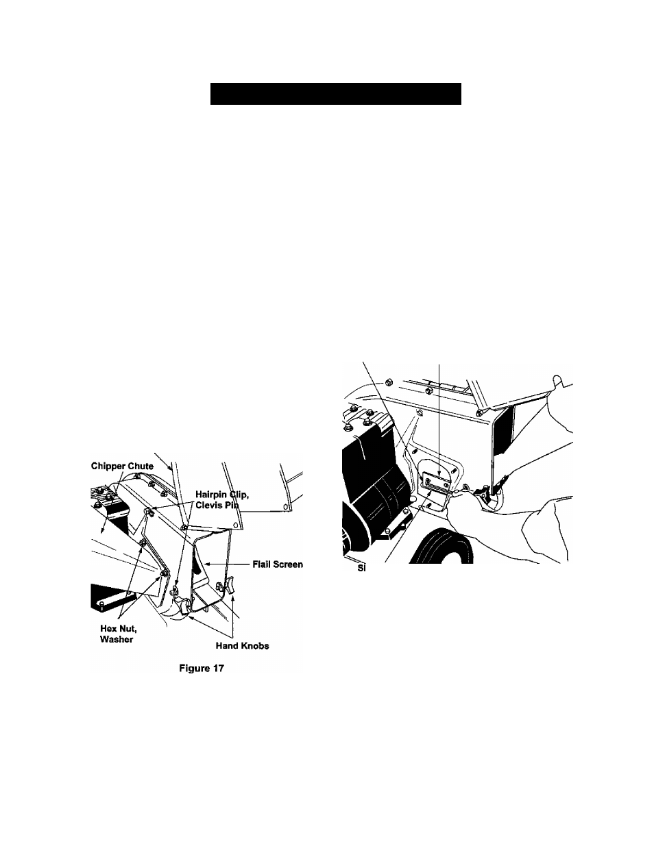
Remove two hairpin clips from the clevis pins
which extend through the housing. Remove the
clevis pins. See figure 17.
•
Pull the flail screen from inside the housing.
See figure 17.
•
Clean the screen by scraping or washing with
water.
•
Reinstall the screen.
•
Put the discharge chute back to its original
position and tighten the hand knobs.
NOTE: Be certain to reassemble the flail screen wifli
the curved side down.
Chute Deflector
SHARPENING OR REPLACING
THE BLADES
Chipper Blades
• Disconnect spark plug wire and move it away
from spark plug.
•
Remove the flail screen as instructed in previous
section.
•
Using a 1/2” wrench, remove the chipper chute
by removing three hex nuts and washers. See
figure 17.
•
Using a 7/16” wrench, remove the brace
(holding the chute to the frame) by removing the
hex bolts.
NOTE: When re-assembling, the cupped washer
goes on the slot toward the bottom of the chipper
chute with the cupped side against the chute.
•
Rotate the impeller assembly by hand until you
locate one of the two chipper blades in the
chipper chute opening. Remove the blade, using
a 3/16" alien wrench on the outside of the blade
and 1/2" wrench on the impeller assembly
(inside the housing). See figure 18.
Slot
Blade
fiarp Edge
Figure 18
•
Remove the other blade in the same manner.
•
Replace or sharpen blades.
•
If sharpening, make certain to remove an equal
amount from each blade.
•
Reassemble in reverse order. Make certain
blades are reassembled with the sharp edge
facing the direction shown in figure 18 (sharp
edge is assembled toward the slotted opening at
the bottom).
•
Torque bolts and nuts to 250-350 inch-pounds.
Shredding Blade
The shredding blade may be removed for sharpening
or replacement as follows.
15