Unpacking, Inserting batteries into the remote, Hookup overview – Sony TA-AV571 User Manual
Page 4: Before you get started, Unpacking hookup overview
Attention! The text in this document has been recognized automatically. To view the original document, you can use the "Original mode".
Unpacking
Check that you received the tollowing items with the
amplitier:
• Remote controller (remote) (1)
• Size AA (R6) batteries (2)
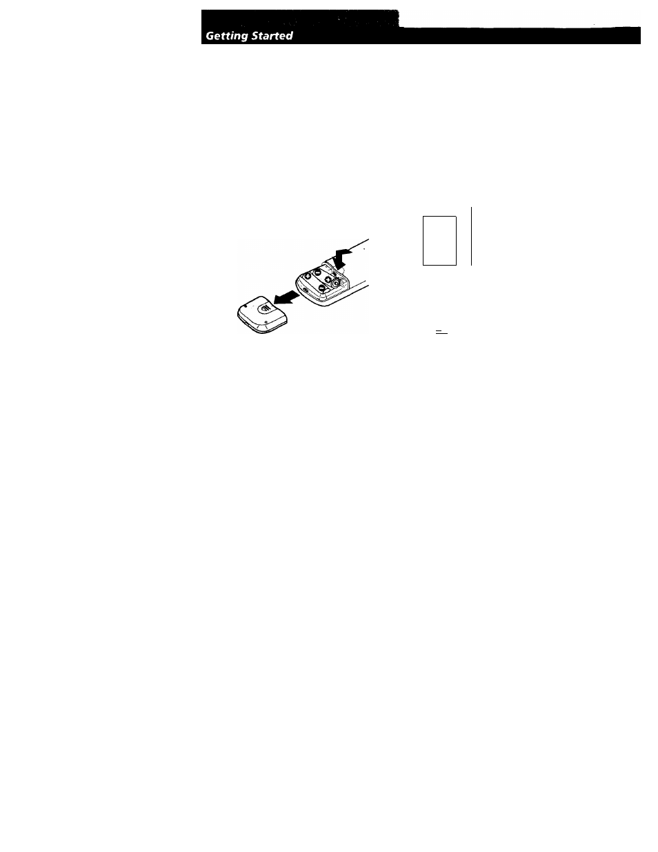
Inserting batteries into the remote
Insert two size AA (R6) batteries in accordance with
the + and - marking on the battery compartment.
When using the remote, point it at the remote sensor
I
on the amplifier.
'Q'
When to replace batteries
Under normal use, the batteries should last for about
6 months. W hen the remote no longer operates the
amplifier, replace both batteries with new ones.
Notes
• Do not leave the remote in an extrem ely hot or hum id
place.
• Do not use a new battery with an old one.
• Do not expose the remote sensor to direct sunlight or
lighting apparatuses. Doing so may cause a malfunction.
• If you don't use the remote for an extended period of time,
rem ove the batteries to avoid possible damage from
battery leakage and corrosion.
Hookup Overview
The amplifier allows you to connect and control the
following audio/ video components. Follow the
hookup procedures on the specified pages for the
components that you want to connect to the amplifier
To learn the locations and names of each jacks, see
"Rear Panel Descriptions" on page 18.
Speaker
System
Hookups
Audio/Video
Component
Hookups (see page 5)
(see page 6)
Front
speaker
(L)
VCR
LD player
TV game
Center
speaker
Front
speaker
(R)
□
O
V- I-
o
CD player
Rear
speaker
(U
Tape deck
Tuner
Rear
speaker
(R)
Turntable
Audio/Video
Component
Hookups (see page 5)
Before you get started
• Turn off the power to all components before making
any connections.
• Do not connect the AC power cords until all of the
connections are completed.
• Be sure to make connections firmly to avoid hum
and noise.
• When connecting an audio cable, be sure to match
the color-coded pins to the appropriate jacks on the
components: White (left, audio) to White; and Red
(right, audio) to Red.