Optional equipment for steam boilers – Chromalox CHPES-6A User Manual
Page 15
OPTIONAL EQUIPMENT FOR STEAM BOILERS
IF A CONTROLLER SEEMS TO OPERATE IMPROPERLY
If the controller is suspected of operating improperly, it may be
further checked as follows:
1. Leave the controller installed where it is, but disconnect all power
to the boiler.
2. Loosen the cover screw below the main scaleplate and remove the
cover.
3. Disconnect the wires from the controller.
4. Connect an ohmmeter between controller terminals B and W to
measure the resistance of the potentiometer in the controller. The
ohmmeter should read about 135 ohms on an L91B.
5. Connect the ohmmeter between controller terminals W and R and
raise the set point of the controller above the actual pressure being
measured. The ohmmeter should read the full value of the poten-
tiometer measured in step 4 (135 ohms for an L91B).
6. Slowly lower the set point of the controller while observing the
ohmmeter reading. The resistance should drop to zero at some set
point below the actual pressure.
7. An approximation of the proportioning range can be made by
observing the change in set point required for a resistance change
from zero to full value.
8. When the controller is operating properly, reconnect the wires,
replace the cover, tighten the cover screw, and reset the controller
to the desired value.
9. Reconnect power to the controlled motor.
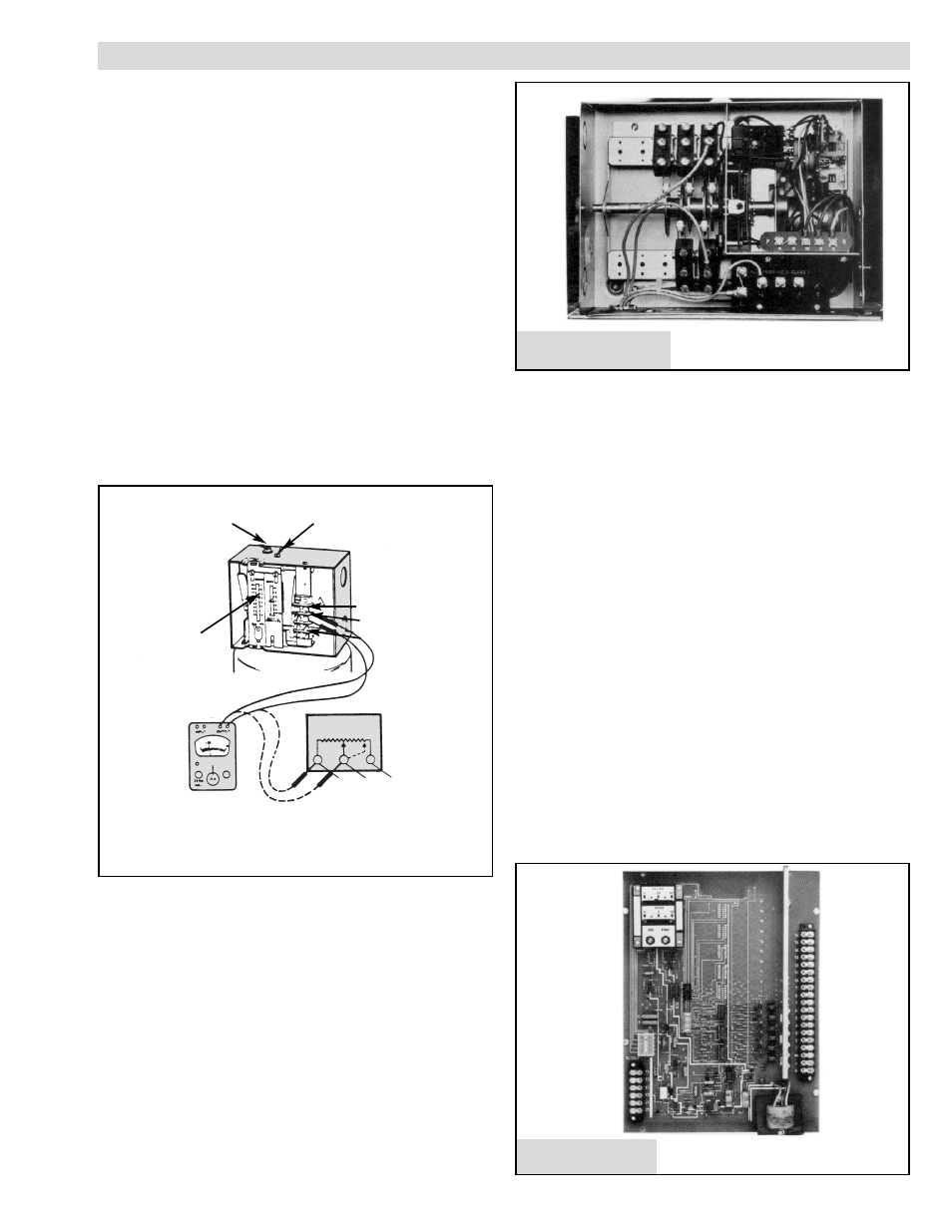
BOILER SEQUENCER (5 STEP) MOTOR DRIVEN
RECYCLE FEATURE
The step control is designed to drop out all contactors when con-
trol circuit is interrupted. On resumption of power, the camshaft
rotates to the counterclockwise (ccw) limit, opening all the load
switches. The recycle relay then energizes, pulling in the load con-
tact, and finally the camshaft rotates clockwise (cw) to the position
called for by the pressure controller energizing, in sequence, the
required load stages.
TESTING OPERATION OF SEQUENCER
1. With boiler off, remove wiring from pressure control on
sequencer low voltage terminal board.
2. Turn on boiler to supply the voltage to the sequencer. Short ter-
minal R and B for counterclockwise rotation and terminal R and
W for clockwise rotation.
3.
If sequencer operates under this test procedure, but when rewired
to pressure controller and does not function, check pressure con-
trol. Note that wiring is W-B and B-W-R-R between sequencer
and pressure controller
BOILER SEQUENCE — SOLID STATE
Solid State Progressive Sequencer
The solid state progressive sequencer provides accurate elec-
tronic control of multi-stage loads of the type used in Chromalox
steam boilers. It features progressive sequencing (first on-first off)
which equalizes the operating time of each load. This control gives
visual indication of each energized stage by means of integral solid
state light emitting diodes. In the event of power interruption, all
heating elements are immediately de-energized for safety. When
power resumes, the control will restage the loads one at a time.
The solid state sequencer operates on 120V AC/60 Hz and each
output is relay switched with a load rating of 125 VA at 120V AC.
The input to the sequencer is a 0-135 OHM potentiometer sup-
plied on the operating pressure control. The sequencer has a sensi-
tivity control which is adjustable from min. to max. This sensitivity
control defines the amount of resistance (pressure) deviation
allowed before adding or subtracting a load. Potentiometer resis-
tance should decrease with increasing pressure. Connections are
made to red and white terminals of proportional pressure control.
See Wiring Diagram 337-300164-452 for Boiler With Solid State
Sequencer.
Main Scale
Adjusting
Screw
Proportioning Range
Adjusting Screw
R
W
B
Main Scale
Setting
Indicator
Set Point
Increase
R
W
B
Ohmmeter
Increases to
135 Ohms
Terminals are not Labeled, but Screw-Heads are
Color Coded Red (R), White (W) and Blue (B).
15
Solid State Sequencer
Sequencer (5-Step)