Carrier 38BRC User Manual
Page 4
Relieve pressure and recover all refrigerant before system
repair or final unit disposal to avoid personal injury or death.
Use all service ports and open all flow control devices,
including solenoid valves.
SEQUENCE OF OPERATION
Turn on power to indoor and outdoor units. Transformer is
energized.
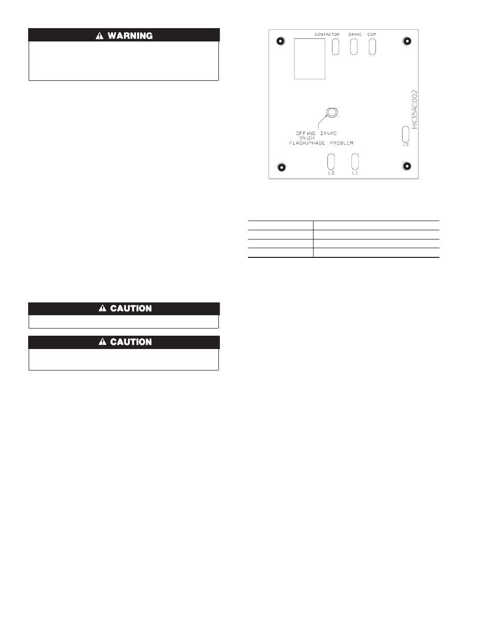
On a call for cooling, thermostat makes circuits R-Y and R-G. On
three phase models with scroll compressors, the units are equipped
with a phase monitor to detect if the incoming power is correctly
phased for compressor operation. (See Fig. 4 and Table 2.) If the
phasing is correct, circuit R-Y energizes contactor, starting out-
door fan motor and compressor circuit. R-G energizes indoor unit
blower relay, starting indoor blower motor on high speed.
NOTE:
If the phasing is incorrect, the contactor will not be
energized. To correct the phasing, interchange any two of the three
power connections on the field side.
When thermostat is satisfied, its contacts open, de-energizing
contactor and blower relay. Compressor and motors stop.
If indoor unit is equipped with an off-delay circuit, the indoor
blower can run up to an additional 120 sec to increase system
efficiency.
Step 11—Check Charge
UNIT CHARGE
Factory charge is shown on unit rating plate. Charge procedure is
shown on wiring/charging label located on unit.
Compressor damage may occur if system is overcharged.
Do not vent refrigerant to atmosphere. Recover during system
repair or final unit disposal.
CARE AND MAINTENANCE
For continuing high performance, and to minimize possible
equipment failure, it is essential that periodic maintenance be
performed on this equipment. Consult your servicing contractor or
User’s Manual for proper frequency of maintenance. Frequency of
maintenance may vary depending upon geographic areas, such as
costal applications.
Leave User’s Manual with homeowner. Explain system operation
and maintenance procedures outlined in manual.
Fig. 4—3 Phase Monitor Control
A00010
Table 2—Phase Monitor LED Indicators
LED
STATUS
OFF
No call for compressor operation
FLASHING
Reversed phase
ON
Normal
4