Carrier 38BRC User Manual
Page 2
Step 4—Operating Ambients (Outdoor Temperatures)
The minimum outdoor operating ambient in cooling mode is 55°F,
and the maximum outdoor operating ambient in cooling mode is
125°F.
Step 5—Replace Indoor AccuRater® Piston, If Required
Check indoor coil piston to see if it matches the required piston
shown on outdoor unit rating plate. If it does not match, replace
indoor coil piston with piston shipped with outdoor unit. The
piston shipped with outdoor unit is correct for any approved indoor
coil combination.
Step 6—Make Refrigerant Tubing Connections
Outdoor units may be connected to indoor sections using accessory
tubing package or field-supplied refrigerant grade tubing of correct
size and condition. For tubing requirements beyond 50 ft, consult
Application Guideline and Service Manual—Air Conditioners and
Heat Pumps Using R-22 Refrigerant. Connect tubing to fittings on
outdoor unit vapor and liquid service lines. (See Table 1.)
If refrigerant tubes or indoor coil is exposed to atmospheric
conditions for longer than 5 minutes, it must be evacuated to 500
microns to eliminate contamination and moisture in system.
OUTDOOR UNIT CONNECTED TO FACTORY-APPROVED
INDOOR UNIT
Outdoor unit contains correct system refrigerant charge for opera-
tion with indoor unit of same size when connected by 15 ft of
field-supplied or factory accessory tubing. Check refrigerant
charge for maximum efficiency. (See Procedure 11–Check
Charge.)
To avoid valve damage while brazing, service valves must be
wrapped with a heat-sinking material such as a wet cloth.
SWEAT CONNECTION
Use refrigerant grade tubing. Service valves are closed from
factory and ready for brazing. After wrapping service valve with a
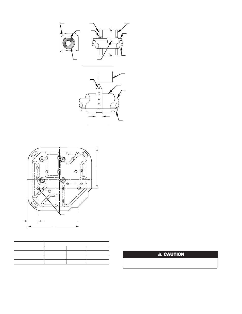
Fig. 1—Connecting Tubing Installation
A94028
INSULATION
VAPOR TUBE
LIQUID TUBE
OUTDOOR WALL
INDOOR WALL
LIQUID TUBE
VAPOR TUBE
INSULATION
CAULK
Avoid contact between tubing and structure
NOTE:
THROUGH THE WALL
HANGER STRAP
(AROUND VAPOR
TUBE ONLY)
JOIST
1
″
MIN.
SUSPENSION
Fig. 2—Mounting Unit to Pad
Dimensions (In.)
UNIT BASE
DIMENSIONS
TIEDOWN KNOCKOUT LOCATIONS
A
B
C
18 X 18
3
15
10-3/16
22-1/2 X 22-1/2
3-11/16
18-1/8
14-3/8
30 X 30
6-1/2
23-1/2
20
A94199
C
B
A
3
⁄
8
″
D. (9.53) TIEDOWN
KNOCKOUTS (2) PLACES
2