Carrier 38BRC User Manual
Page 3
wet cloth, braze sweat connections using industry accepted meth-
ods and materials. Consult local code requirements. Refrigerant
tubing and indoor coil are now ready for leak testing. This check
should include all field and factory joints.
Step 7—Make Electrical Connections
To avoid personal injury or death, do not supply power to unit
with compressor terminal box cover removed.
Be sure field wiring complies with local and national fire, safety,
and electrical codes, and voltage to system is within limits shown
on unit rating plate. Contact local power company for correction of
improper voltage. See unit rating plate for recommended circuit
protection device.
NOTE:
Operation of unit on improper line voltage constitutes
abuse and could affect unit reliability. See unit rating plate. Do not
install unit in system where voltage or phase imbalance (3 phase)
may fluctuate above or below permissible limits.
NOTE:
Use copper wire only between disconnect switch and
unit.
NOTE:
Install branch circuit disconnect of adequate size per
NEC to handle unit starting current. Locate disconnect within sight
from and readily accessible from unit, per Section 440-14 of NEC.
ROUTE GROUND AND POWER WIRES
Remove access panel to gain access to unit wiring. Extend wires
from disconnect through power wiring hole provided and into unit
control box.
According to NEC, ANSI/NFPA 70, and local codes, cabinet
must have an uninterrupted or unbroken ground to minimize
personal injury if an electrical fault should occur. The ground
may consist of electrical wire or metal conduit when installed
in accordance with existing electrical codes. Failure to follow
this warning can result in an electric shock, fire, or death.
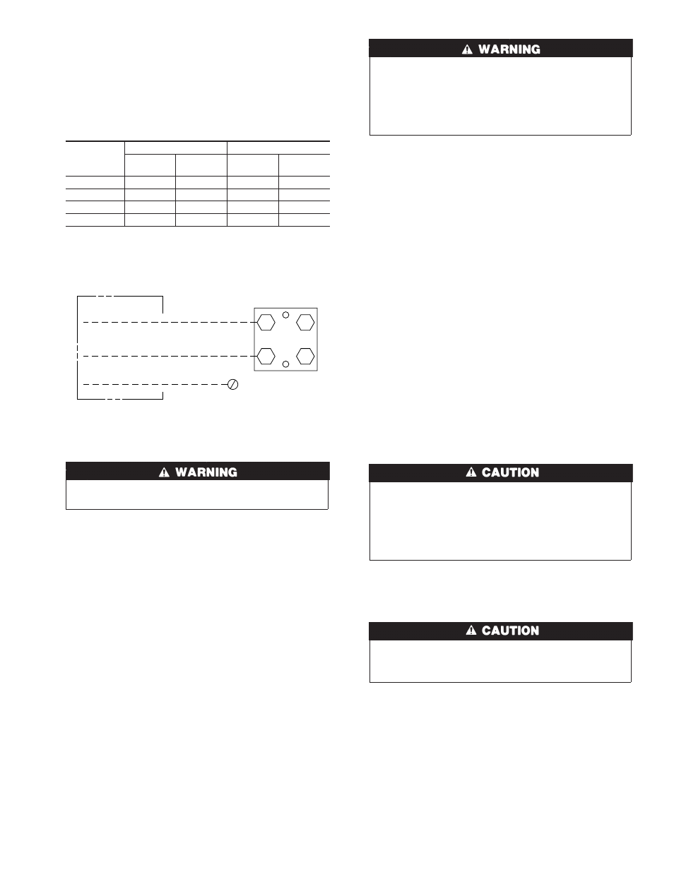
CONNECT GROUND AND POWER WIRES
Connect ground wire to ground connection in control box for
safety. Connect power wiring to contactor as shown in Fig. 3.
CONNECT CONTROL WIRING
Route 24v control wires through control wiring grommet and
connect leads to control wiring. (See Fig. 5.) Use No. 18 AWG
color-coded, insulated (35°C minimum) wire. If thermostat is
located more than 100 ft from unit, as measured along the control
voltage wires, use No. 16 AWG color-coded wire to avoid
excessive voltage drop.
Use furnace transformer, fan coil transformer, or accessory trans-
former for control power, 24v/40va minimum.
NOTE:
Use of available 24v accessories may exceed the mini-
mum 40va power requirement. Determine total transformer load-
ing and increase the transformer capacity or split the load with an
accessory transformer as required.
Step 8—Compressor Crankcase Heater
A crankcase heater is required if refrigerant tubing is longer than
50 ft.
Step 9—Install Electrical Accessories
Refer to the individual instructions packaged with kits or acces-
sories when installing.
Step 10—Start-Up
• 3-phase scroll compressors are rotation sensitive.
• A flashing LED on phase monitor indicates reverse rotation.
(See Fig. 4 and Table 2.)
• This will not allow contactor to be energized.
• Disconnect power to unit and interchange 2 field wiring
leads on unit contactor.
1. When equipped with a crankcase heater, energize heater a
minimum of 24 hr before starting unit. To energize heater
only, set thermostat to OFF mode and close electrical discon-
nect to outdoor unit.
Service valve gage ports are equipped with Schrader valves.
To prevent personal injury, wear safety glasses and gloves
when handling refrigerant.
2. Fully back seat (open) liquid and vapor service valves.
3. Unit is shipped with valve stem(s) front seated (closed), and
caps installed. Replace stem caps after system is opened to
refrigerant flow. Replace caps finger-tight and tighten addi-
tional 1/6 turn with wrench.
4. Close electrical disconnects to energize system.
5. Set room thermostat at desired temperature. Be sure set point
is below indoor ambient temperature.
6. Set room thermostat at COOL and fan ON or AUTO modes,
as desired. Operate unit for 15 minutes. Check system
refrigerant charge. See Check Charge section.
Table 1—Refrigerant Connections
and Recommended
Liquid and Vapor Tube Diameters (In.)
UNIT SIZE
LIQUID
VAPOR
Connect
Diameter
Tube
Diameter
Connect
Diameter
Tube
Diameter
018, 024
3/8
3/8
3/8
5/8
030, 036
3/8
3/8
3/8
3/4
042-048
3/8
3/8
7/8
7/8
060
3/8
3/8
7/8
1-1/8
Note: Tube diameters are for lengths up to 50 ft. For tubing lengths greater
than 50 ft, consult your local distributor or Long-Line Application Guideline.
Fig. 3—Line Power Connections
A88174
CONTACTOR
DISCONNECT
PER N.E.C. AND/OR
LOCAL CODES
FIELD POWER
WIRING
FIELD GROUND
WIRING
GROUND
LUG
3