Taylor-Wharton LS Series User Manual
Page 6
Changing Liquid Level
The liquid level in the unit is determined by the position of
the sensor probes in the sensor tube next to the fill tube.
These probes have been set at installation to maintain a
specific liquid level. The controller operates a fill cycle that
adds liquid at low level, fills to a predetermined high level,
then stops the fill. The cycle repeats when liquid drops to
the low level over time.
Sensor probe positions may be changed to define new high
and low liquid levels, and these levels may be set indepen-
dently to vary the liquid level differential between fills. If a
higher liquid level is desired, withdraw the sensor tube; for a
low level, the sensors must be moved further into (down)
the sensor tube.
CAUTION: Ice or frost in the sensor
tube may restrict movement of
sensor probes in the tube. Do not
pull excessively on sensor wiring
while attempting to change sensor
position. It may be necessary to
remove the sensor from the con-
tainer and allow it to thaw before the
sensor can be repositioned.
Increasing the distance between low and high sensor
probes allows greater liquid level fluctuation, less frequent
filling and reduced fill loses; decreasing the distance has
the opposite effect.
To set the liquid level to a different point, or to change the
level differential, the sensors must be repositioned. Their
position within the sensor tube is held in place by the
sensor tube plug, which is split to allow the sensor leads to
pass through. The sensor tube plug holds the sensors at
the position necessary to maintain a specific liquid levels.
Two different sensor heights are specified by their position
within the sensor tube. The low and high sensor pods are
separately positioned to set the liquid levels at which the
controller will start or terminate each fill cycle. Insert the
sensor leads into the perforated sensor tube to the desired
height. Mark the sensor leads at the top of the sensor tube.
Pull the leads out just enough to install the sensor tube plug
around the marks on the sensor leads. Insert sensor plug
securely into the mouth of the tube. Perform this operation
carefully, so the sensor leads are not damaged.
NOTE:
The high level sensors must be at least
1.75 in. (5.1 cm) above the low level
sensor pod.
After repositioning sensors, check to be sure the sensor
tube is secured to the fill tube and the sensor wires are
dressed and clear of rack operation, and turn the controller
on. The controller should fill the refrigerator to the new
liquid level. After sensors are repositioned, the controller
should maintain the liquid pool at the new operating level.
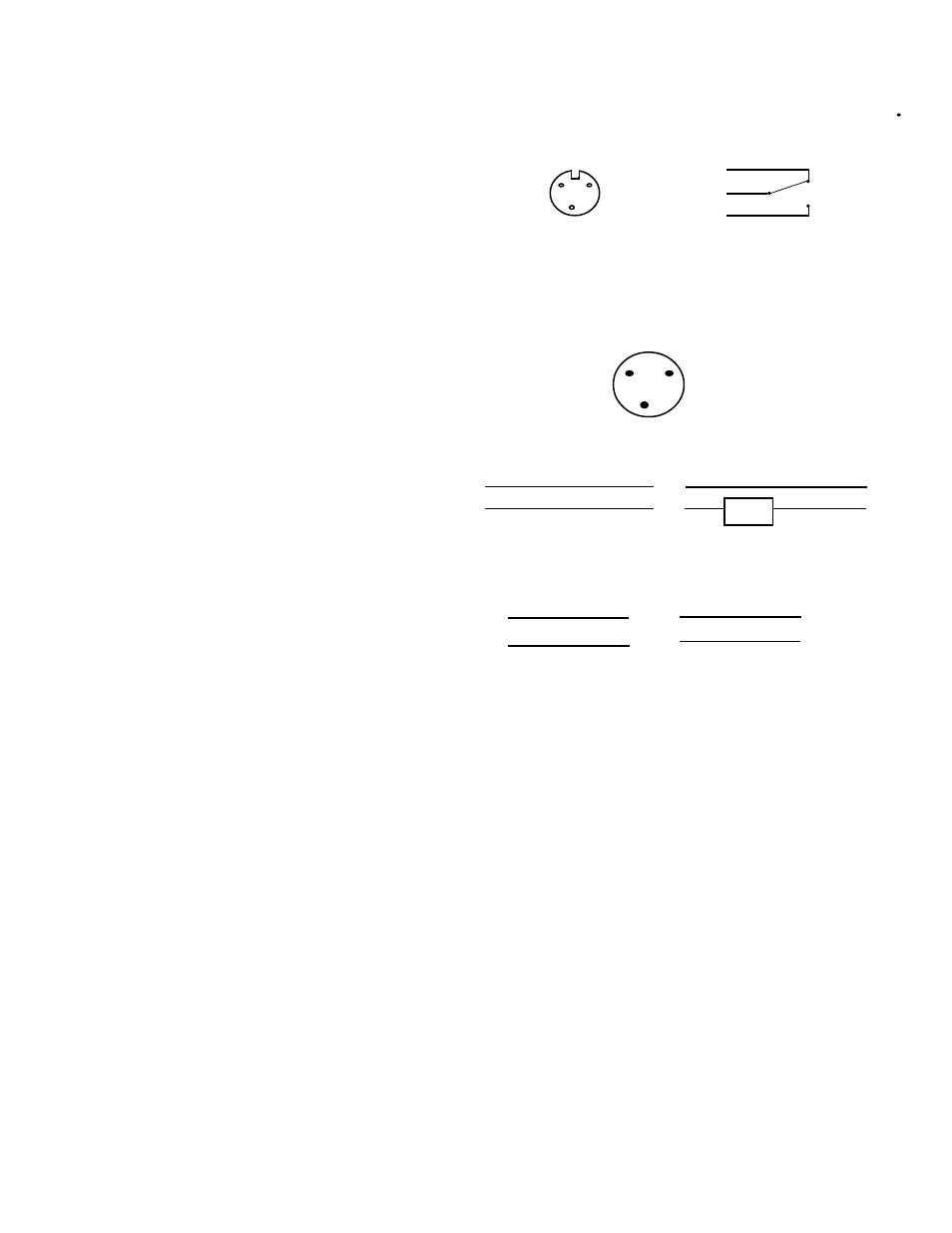
Remote Alarm Connection
Relay connections are provided on an external for user
installation of a remote alarm circuit (see Figure 8.) Wiring
external power supply and alarm devices must be supplied
by the user. During an alarm condition, contacts 1 & 2 are
closed and contacts 2 & 3 are open.
Remote Alarm Connection on Taylor-Wharton Freezers
Back panelson most Taylor-Wharton freezers are equipped
with a 3 point electrical socket. The socket connects to a
control board mounted, SPDT (single pole double throw)
relay, rated at 10 amps, 125 VAC.
A Switchcraft plug (#05GM3M) connects to the above
socket. It is available with leads as Taylor-Wharton part
#R06K-8C20. Approximately 9 of wire extend from the
plug. The gray wire connects to Pin #1, orange wire to Pin
#2 and the purple wire to Pin #3.
To connect an AC load, such as an alarm light or buzzer,
connect as shown below:
For automatic dialers and other alarm systems that are
alarmed on either a contact make or break, connect as
shown below:
MAINTENANCE
LS Series CryoStorage Maintenance
Defrosting your K Series CryoStorage System
All liquid nitrogen storage systems are subject to ice and
frost buildup over time. Regular preventive maintenance
programs should be instituted to remove ice and frost from
the sensor and fill tubes and from the refrigerator lid.
Ice and frost build up in the sensor tube may result in false
readings being relayed to the controller from the sensors.
Ice can form a thermal barrier around a level sensor,
rendering it insensitive to the temperature differences
between vapor and liquid. Sensors and thermocouple
should be removed regularly and inspected for ice and frost
build up.
NOTE:
Ice or frost in the sensor tube may restrict
the movement of sensor probes in the
tube. Do not pull excessively on the sensor
wiring while attempting to change sensor
position. It may be necessary to remove
the fill tube and tube from the container
and allow it to thaw before the sensors can
be repositioned.
~
~
AC Line
AC Line
orange
gray
Alarm
orange
purple
2
3
1
2
orange
gray
Alarm on break
Alarm on make
1
2
3
1
2
3
1
3 (NO)
(NC)
3
2
1