Taylor-Wharton LS Series User Manual
Page 4
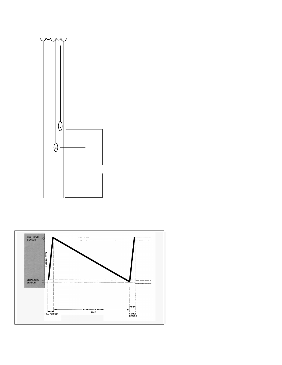
Figure 2. Sensor Positioning for the AutoTend
.25 inches
Figure 4. Normal Fill/Evaporation Cycle Chart
CONTROLLER OPERATION
Introduction
The AUTO-TEND Control System is designed to provide
simple, reliable liquid level control in your LN
2
freezer. It
operates on 24 Volts AC and uses a two-sensor system to
open and close a solenoid valve. The liquid level, the sensor
condition, the valve condition, and the LN
2
supply condition
are indicated by lights on the front panel.
Installation:
The AUTO-TEND Control System is designed to mount
onto your Taylor-Wharton Cryogenic refrigerator. The
components plug into the back of the control panel as
follows: The Solenoid Valve has a 2-pin connector. The
sensor assembly has a 4-pin connector. These plug into the
mates on the back of the control panel.
The sensor assembly should be installed with the yellow
and orange wires at the High Level and the black and red
wires at the Low Level. These are labeled for easy refer-
ence.
The Auto-Tend controller should not require additional
attention to maintain liquid level if an adequate supply of
liquid nitrogen is maintained. If your protocol calls for you to
top off the cryostorage system at the end of a work day or
work week, press the Start button. The unit will fill to the
upper allowable liquid level and stop automatically. You may
choose to manually stop the fill by pressing the STOP
button at anytime during the fill.
Normal Fill Cycle
When the unit is filled and the controller is operating, the low
level sensor is immersed in liquid nitrogen (see Figure 4.)
Its resistance value is interpreted by the controller as in
liquid. At the same time, the high level sensor is above the
liquid pool sending the controller an in-gas signal. In this
condition, the control panel will read Normal. As liquid
nitrogen evaporates, the liquid level in the refrigerator drops
slowly until the low level sensor is above the liquid and
sends a different signal to the controller. The controller
interprets this condition as low liquid and opens
the fill solenoid valve admitting more refrigerant.
The unit fills slowly, the control panel will read
LOW when the liquid level is above the low
level sensor. It will continue to display the green
filling light until the high level sensor is immersed
in liquid. Once the level of the liquid reaches the
point of the high level sensor, the Solenoid Valve
will close. Figure 4 illustrates this cycle in graph
form where liquid level is plotted against time,
and display graphics are shown as they appear
at key points in the cycle.
Start Fill
2.0 inches
Stop Fill