Current loop cable wiring, Figure 16: current loop wiring diagram (4 wire) – Connect Tech Blue Heat/PCI PCI Serial Communications User Manual
Page 42
Blue Heat/PCI User’s Manual, Connect Tech Inc.
Revision 0.11
42
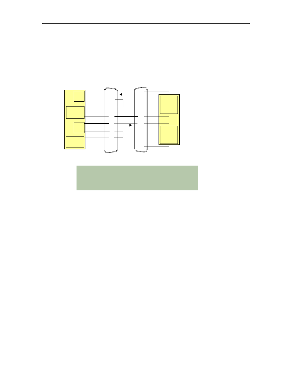
Current Loop Cable Wiring
You can wire Blue Heat/PCI CL adapters in various ways to communicate with 20mA Current
Loop peripherals. A few examples of Current Loop cabling schemes follow.
below depicts a 4 wire cabling scheme between a port on the Blue Heat/PCI CL
adapter to another port on the Blue Heat/PCI CL adapter.
Figure 16: Current Loop wiring diagram (4 wire)
1
8
2
7
RxD +
TxD +
RxD -
TxD -
4
7
9
8
20mA
20mA
TxD +
RxD -
RxD +
TxD -
3
2
6
1
XMTR
HCPL 4100
RCVR
HCPL 4200
TxD Source
TxD Return
RxD Source
RxD Return
I
SRC
Optically isolated station
(Passive transmitters/receivers)
Non-isolated station
(Active transmitters/receivers)
Port 1
DB-9 male
Port 2
DB-9 male
I
SRC
XMTR
HCPL 4100
RCVR
HCPL 4200
Note:
The example above illustrates a 20mA Current Loop cable
wiring configuration between one port of a Blue Heat/PCI CL
adapter and another port of a Blue Heat/PCI CL adapter. This
example shows wiring for both active and passive modes