Table 3: rj-45 pinouts for the blue heat/pci opto – Connect Tech Blue Heat/PCI PCI Serial Communications User Manual
Page 23
Blue Heat/PCI User’s Manual, Connect Tech Inc.
23
Revision
0.11
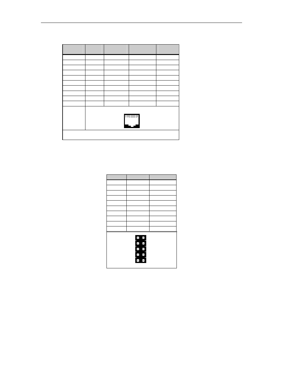
Table 3: RJ-45 pinouts for the Blue Heat/PCI Opto
Pin No.
RS-232
Signal
Direction
RS-422/485
Signal
Direction
1
N/C
no connect
RTS (-)
output
2 N/C
input
RxD
(+)
input
3 RTS
output
RTS
(+)
output
4
SG
signal gnd
SR
signal ref.
5 TxD
output
TxD
(+)
output
6 RxD
input
RxD
(-)
input
7 Gnd
ground
Gnd. ground
8 CTS
input
CTS
(+)
input
9
N/C
no connect
TxD (-)
output
10
N/C
no connect
CTS (-)
input
RJ-45 connector
1
10
Note:
The RS-232 signals do not apply to the Blue Heat/PCI
Opto RS-422/485 adapter
Table 4: Blue Heat/PCI RJ-11 port header (P7/P8) pinouts
Pin No.
RS-232
Direction
1 DCD
input
2 DSR
input
3 RxD
input
4 RTS
output
5 TxD
output
6 CTS
input
7 DTR
output
8 RI input
9 SG signal
gnd.
10 N/C no
connect
4
6
8
10
9
7
5
3
2
1
P7/P8