Half duplex mode, Multi-drop slave mode, Tri-state control – Connect Tech Blue Heat/PCI PCI Serial Communications User Manual
Page 36
Blue Heat/PCI User’s Manual, Connect Tech Inc.
Revision 0.11
36
Half Duplex Mode
In this mode the TxD line driver is enabled only when data is transmitted and RxD is disabled
when data is being transmitted. This mode is typically used in either point to point "2 wire"
connections OR in multi-drop "2 wire" bus connections. To enable this mode for a port you
must jumper positions 7 and 8 on the appropriate jumper blocks JA, JB, JC, JD. These jumpers
short TxD – to RxD – and TxD + to RxD +.
depicts the locations of jumper blocks JA,
JB, JC and JD.
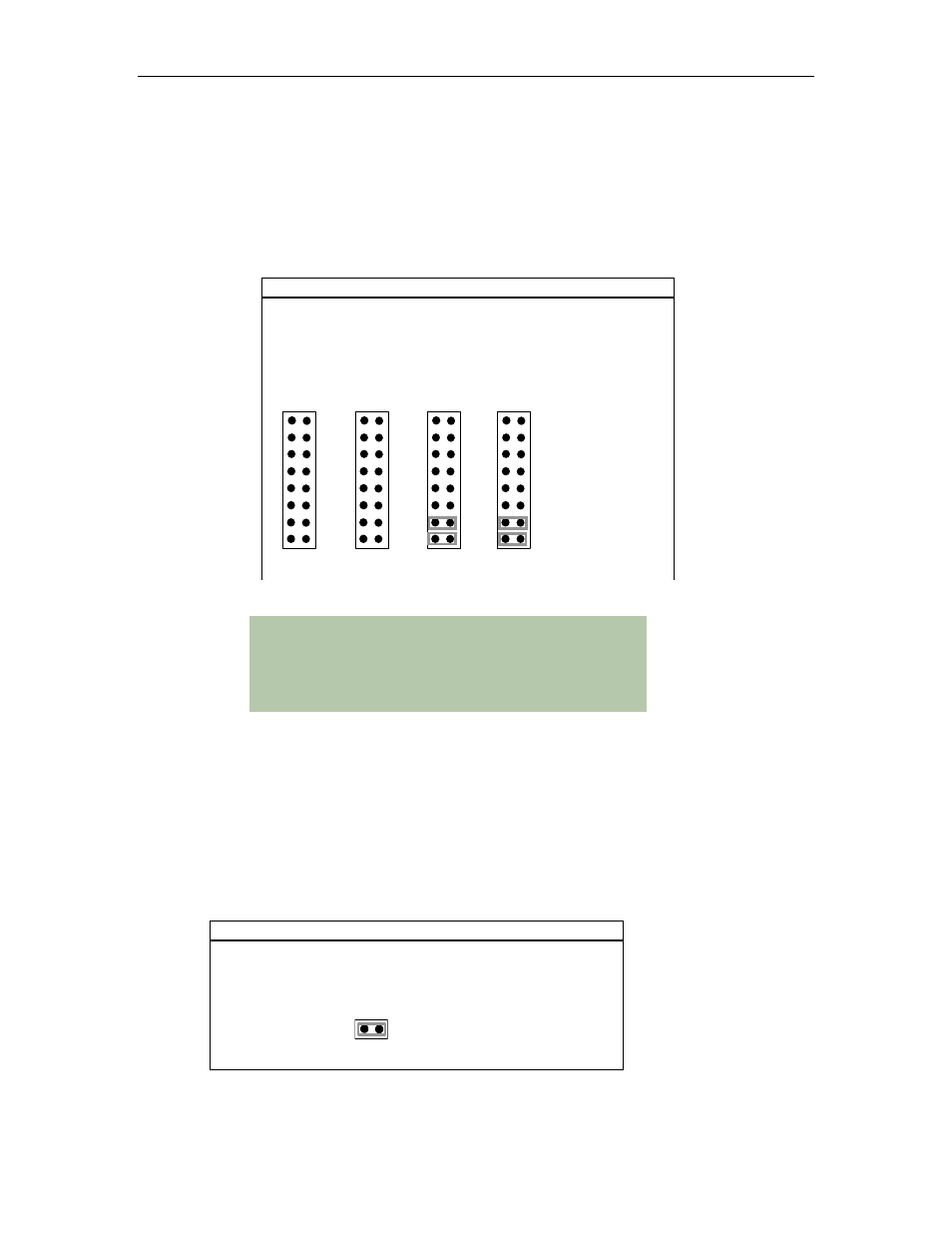
Example
The following example shows the settings on JA, JB, JC and JD
where the RS-422/485 port 1 is set half duplex, the RS-422/485
port 2 is set for half duplex; RS-422/485 port 3 is set for full
duplex or multi-drop slave, and the RS-422/485 port 4 is set for
full duplex or multi-drop slave.
JD1
JB
JC
JD2
JD3
JD4
JD5
JD6
JD7
JD8
JD JA
COM4
JC1
JC2
JC3
JC4
JC5
JC6
JC7
JC8
COM3
JB1
JB2
JB3
JB4
JB5
JB6
JB7
JB8
COM2
JA1
JA2
JA3
JA4
JA5
JA6
JA7
JA8
COM1
RTS ± TERM
TXD ± TERM
CTS ± BIAS
CTS ± BIAS
RXD ± BIAS
RXD ± BIAS
Insert for 1/2 D
Insert for 1/2 D
Technical Notes:
If you wish to set a specific port for half duplex, you must
jumper both positions 7 and 8 on the appropriate jumper block.
For RS-232 ports do not jumper any positions on the
appropriate JA, JB, JC and JD jumper block.
Multi-drop Slave Mode
In this mode the TxD line driver is enabled only when data is transmitted and RxD is enabled all
the time. This mode is typically used in multi-drop "4 wire" connections.
Tri-state Control
The Blue Heat/PCI Opto adapters allow you to tri-state the line drivers on power up. To tri-state
the drivers on power up please make certain there is no jumper installed across the pins on
jumper block JI. Please refer to
for the location of J1.
Example
The following example shows the settings on J1 to tri-state the
transceivers upon power up of the Blue Heat/PCI Opto
adapter.
J1
RS485 TX Power up
ON = ENABLED
OFF = DISABLED
1.