Figure 11 – Connect Tech Blue Heat/PCI PCI Serial Communications User Manual
Page 33
Blue Heat/PCI User’s Manual, Connect Tech Inc.
33
Revision
0.11
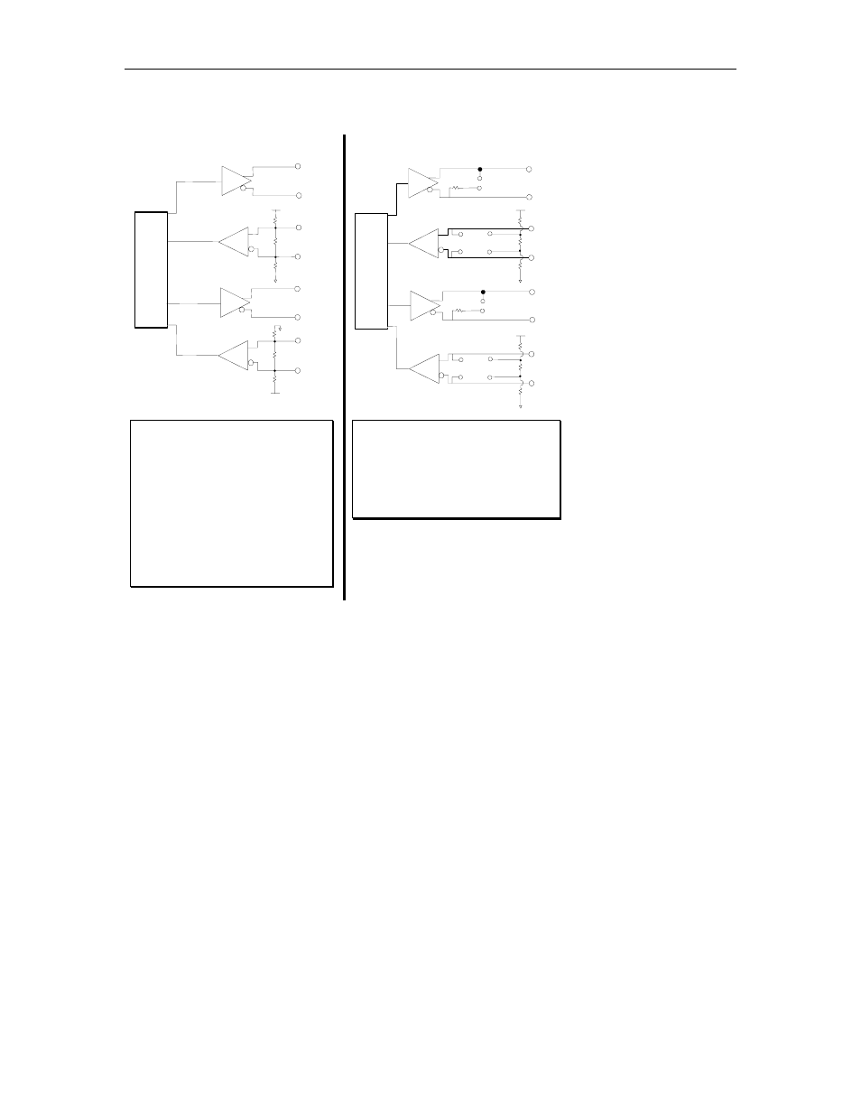
Figure 11: Partial schematic: Blue Heat/PCI RS-422/485; Universal Blue Heat/PCI RS-422-485
TxD
TxD +
RxD -
TxD -
RxD +
Blue Heat/PCI RS-422/485
Universal Blue Heat/PCI RS-422/485
RS-422/485 Line Bias/Termination
RxD
RTS
RTS +
CTS -
RTS -
CTS +
CTS
16C864
UART
150
Ω
1.8K
Ω
1.8K
Ω
+5 V
150
Ω
1.8K
Ω
1.8K
Ω
+5 V
Blue Heat/PCI RS-422/485 (6+2 model)
RS-422/485 Line Bias/Termination
TxD
TxD +
RxD -
TxD -
RxD +
RxD
RTS
CTS
16C864
UART
150
Ω
1.8K
Ω
1.8K
Ω
+5 V
150
Ω
J2, J8
J4, J10
J5, J11
RTS +
RTS -
150
Ω
J3, J9
CTS -
CTS +
150
Ω
1.8K
Ω
1.8K
Ω
+5 V
J4, J10
J5, J11
Note:
1. Line bias and termination is
fixed and permanent.
2. RxD is biased inactive (off,
idle)
3. CTS is biased active (on)
4. For custom line bias and
termination requirements
please contact a Connect Tech
Sales Representative
Note:
1. Line bias and termination is
jumper selectable for the Blue
Heat/PCI RS-422/485 (6+2
model).