System board connectors, Table a – Dell PowerEdge 1600SC User Manual
Page 3
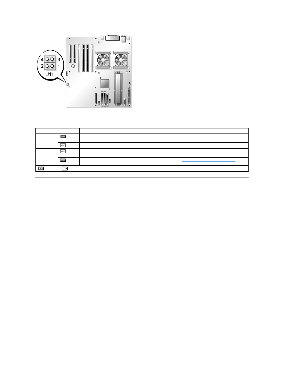
Table A-1. System Board Jumper Settings
System Board Connectors
for the location and description of system board connectors.
also indicates expansion slots and bus operating speeds.
Figure A-3. System Board Connectors
Jumper
Setting
Description
J11 pins 1 and
2
(default)
The password feature is enabled.
The password feature is disabled.
J11 pins 3 and
4
(default)
The configuration settings in NVRAM are retained at system boot.
The configuration settings in NVRAM are cleared at next system boot (see "
Resetting Corrupted BIOS Configuration
" in
"Troubleshooting Your System").
jumpered
unjumpered
See also other documents in the category Dell Computer hardware:
- PowerEdge RAID Controller H700 (178 pages)
- PowerEdge RAID Controller H700 (56 pages)
- PowerEdge RAID Controller H700 (200 pages)
- PowerVault TL2000 (2 pages)
- PowerVault TL4000 (2 pages)
- PowerVault TL2000 (176 pages)
- PowerVault TL2000 (16 pages)
- PowerVault TL2000 (3 pages)
- PowerVault TL2000 (116 pages)
- PowerVault 130T DLT (Tape Library) (49 pages)
- PowerVault TL2000 (1 page)
- PowerVault 110T DLT VS80 (Tape Drive) (49 pages)
- PowerVault TL2000 (22 pages)
- PowerVault TL4000 (306 pages)
- PowerEdge 800 (28 pages)
- PowerEdge 800 (58 pages)
- PowerEdge 800 (87 pages)
- PowerEdge 800 (24 pages)
- PowerEdge 800 (82 pages)
- PowerEdge 800 (2 pages)
- PowerEdge 800 (27 pages)
- PowerEdge 6400 (86 pages)
- PowerVault 124T (73 pages)
- PowerVault 124T (65 pages)
- PowerVault 124T (4 pages)
- PowerVault 124T (79 pages)
- PowerVault 124T (2 pages)
- PowerVault 124T (64 pages)
- PowerVault 124T (56 pages)
- PowerVault 124T (66 pages)
- PowerVault 124T (57 pages)
- PowerVault 110T LTO (Tape Drive) (28 pages)
- PowerVault 124T (55 pages)
- PowerVault TL4000 (3 pages)
- PowerVault TL4000 (176 pages)
- PowerVault TL4000 (2 pages)
- PowerVault TL4000 (16 pages)
- PowerVault TL4000 (116 pages)
- PowerVault TL4000 (1 page)
- PowerVault TL4000 (66 pages)
- PowerVault TL4000 (22 pages)
- PowerEdge RAID Controller 6i (120 pages)
- PowerEdge RAID Controller 6i (156 pages)
- PowerVault 715N (Rackmount NAS Appliance) (44 pages)
- PowerVault 715N (Rackmount NAS Appliance) (30 pages)