Assembly step 4 – Chamberlain 1215EM FS2 User Manual
Page 14
14
ASSEMBLY STEP 4
For Sliding and Swinging Gates Only
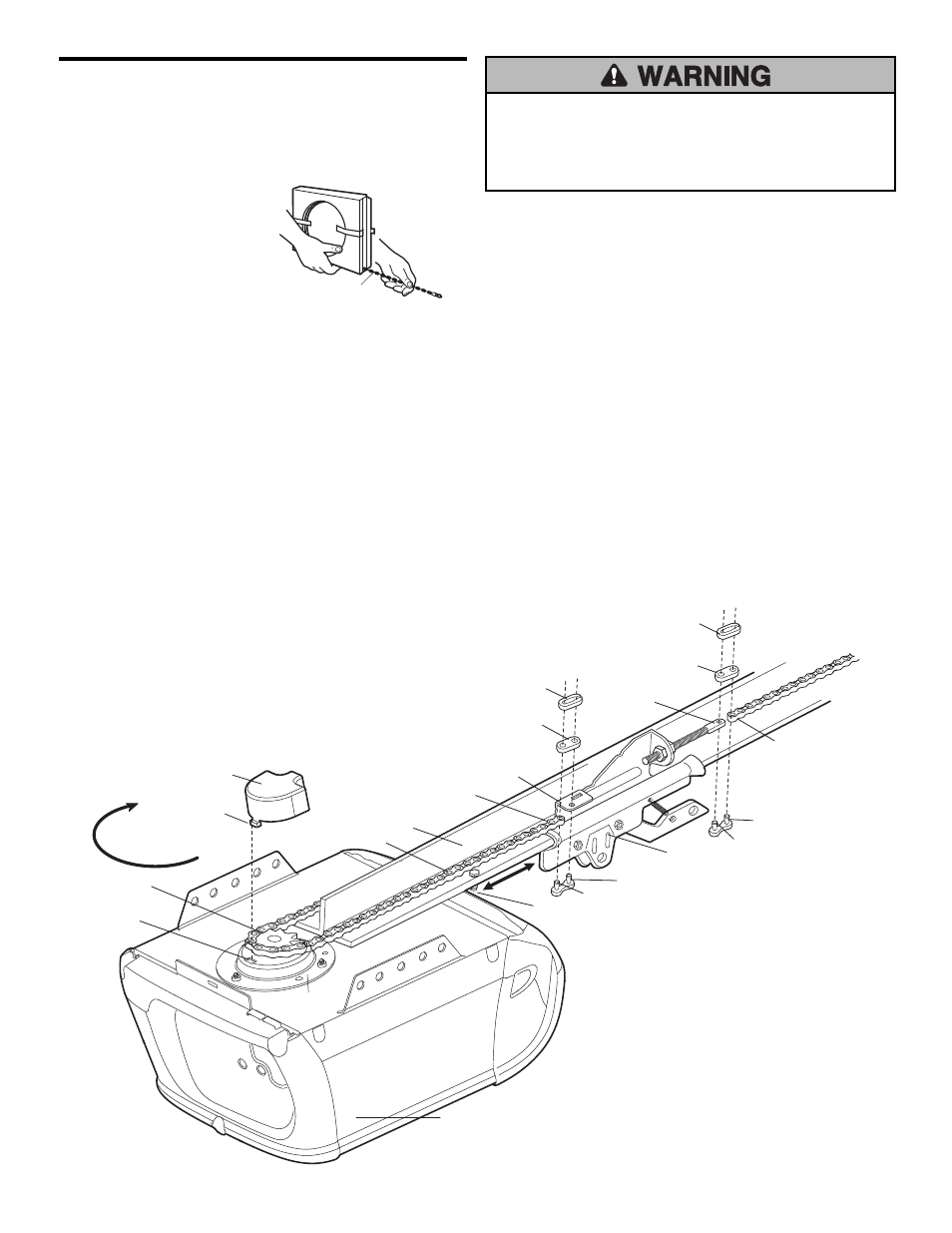
Install the Chain and Attach the
Sprocket Cover
INSTALLING THE CHAIN
1. Dispense a few inches of
chain from carton and fasten
to trolley with a master link
from the hardware bag.
(Figure 1).
•
Push pins of master link
bar through chain link and
hole in front end of trolley.
•
Push master link cap over pins and past pin notches.
•
Slide clip-on spring over cap and onto pin notches until
both pins are securely locked in place.
2. To prevent the trolley from jamming against the opener
during operation, position trolley 5 to 15 cm from the
stop hole as shown. Then dispense the chain around
the opener sprocket (Figure 1). Make sure the sprocket
teeth engage the chain.
•
Proceed around to the pulley bracket and forward to
the threaded trolley shaft.
3. Use the second master link to connect the chain to the
flat end of the shaft (Figure 1). Check to make sure the
chain is not twisted.
ATTACHING THE SPROCKET COVER 1215EM ONLY
Insert the back tab in the slot on the back of the mounting
plate. Squeeze the cover slightly and insert the front tab.
To avoid possible SERIOUS INJURY to fingers from moving
opener:
• ALWAYS keep hand clear of sprocket while operating opener.
• Securely attach sprocket cover BEFORE operating.
Leave Chain
& Cable
Inside Carton to
Prevent Kinking
Keep Chain
Taut When Dispensing
Sprocket
Motor Unit
Back
Tab Slot
Mounting
Plate
Install Chain
in this Direction
Master
Link Pin
Master Link
Clip-On Spring
Master Link
Clip-On Spring
Flat End
of Trolley
Trolley
Pin Notch
Flat End of
Threaded Shaft
Master
Link Cap
Rail
Master
Link Cap
Chain
Back Tab
Sprocket
Cover
Chain Link
Trolley Stop
(Hex Bolt)
5-15 cm
Pin Notch
Master
Link
Pin
Chain Link
Figure 1