Nvb series b-vent gas fireplace, Remote wall switch, R models – Vermont Casting NVBR36 User Manual
Page 9: Honeywell ignition, Fig. 8 typical gas supply installation, Pilot thermodisk on/off switch valve, Thermodisk
9
NVB Series B-Vent Gas Fireplace
7412950
24 VAC HOT
24 VAC RTN
ON-OFF
SWITCH
NOVA SIT 822 VALVE
HONEYWELL S8600 B IGNITION MODULE
120 VAC RTN
40VA
TRANSFORMER
120 VAC HOT
BLACK
BLACK
BLACK
BLACK
BLACK
BLACK
BLACK
WHITE
WHITE
WHITE
WHITE
WHITE
WHITE
WHITE
WHITE
BLACK
FP670
NOVA SIT 822 VALVE WIRING DGRM.
��������������������������������������
4/30/98
PILOT
��
�
���
����
���
���
���
�
�
����
����
����
�
��
���
���
��
��
��
���
����
�������
������
�
�
�
�����
���
1 5
3 4
GREEN
MV MVPV PV GND
(BURNER)
24V
24V
SENSE
SPARK
U.S.: Consult the current National Fuel Gas Code,
ANSI Z223.1/NFPA 54.
Canada: CSA - B149.1 installation code.
Test for leaks. Use a 50/50 solution of liquid soap and
water to test for leaks at gas fittings and joints. Apply
water/soap solution with brush only - do not over apply.
NEVER test with an open flame.
The gas control is equipped with a captured screw type
pressure test point, therefore it is not necessary to pro-
vide a 1/8" test point up stream of the control.
When using copper or flex connector use only ap-
proved fittings. Always provide a union so that gas
line can be easily disconnected for burner or fan servic-
ing. See gas specification for pressure details and
ratings. NOTE: If flex connector is used, it must be kept
inside of the appliance. (Fig. 8)
1/2" Gas Supply
1/2" x 3/8" Shut-off Valve
3/8" Union
3/8" Nipple
3/8"
Nipple
GF598
nvb GAS SUPPLY INSTALL
12/4/97
FP598
Fig. 8 Typical gas supply installation.
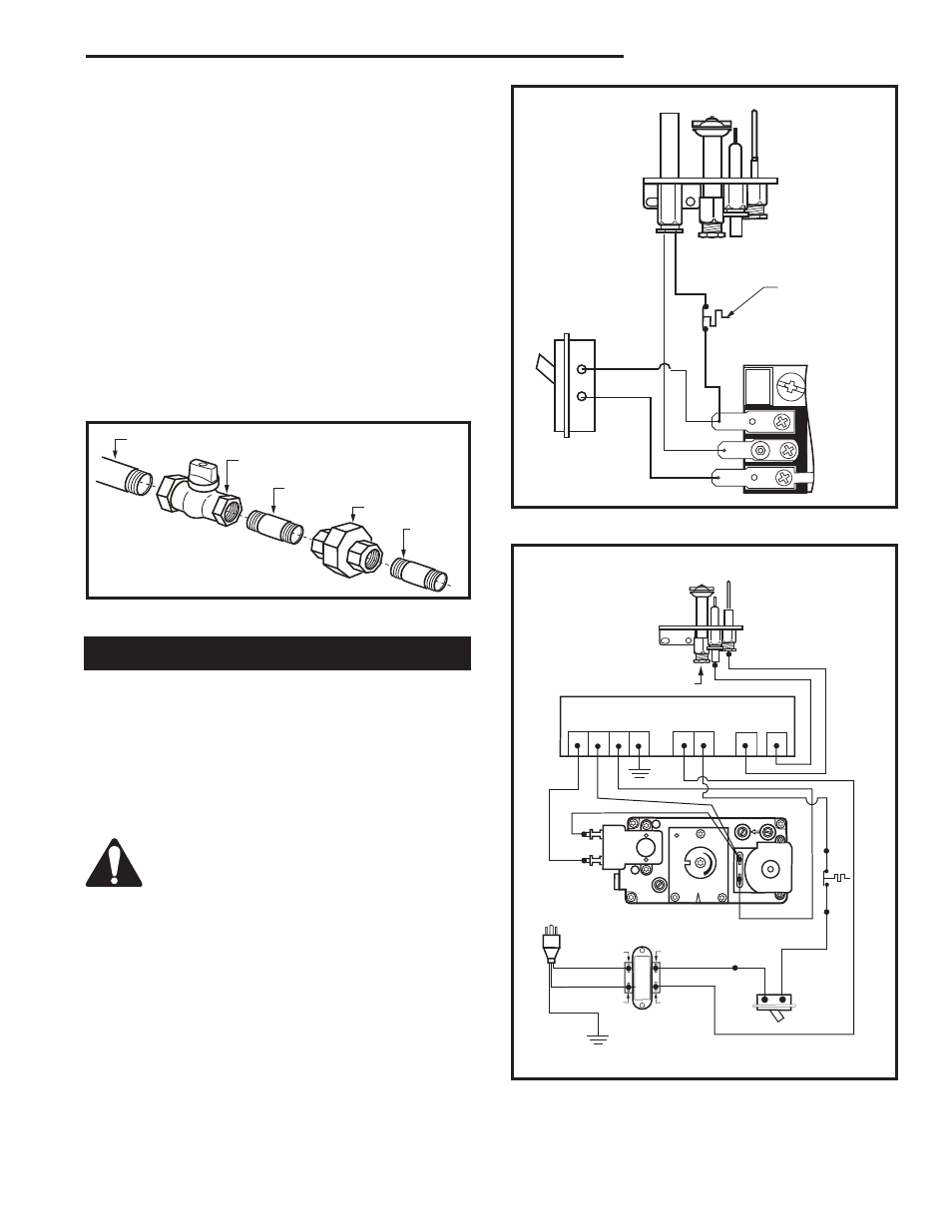
Remote Wall Switch
1. Thread wire through the electrical knockout located
on side of unit. Do not cut wire or insulation on metal
edges. Ensure that wire is protected. Run the other
end to a conveniently located wall receptacle box.
2. Attach wire to switch and install switch into receptacle
box. Attach cover plate to switch.
3. Connect wiring to gas valve. Refer to Figure 9 or 10.
CAUTION: Do not wire millivolt remote
wall switch for gas appliance to a 120v
power supply.
For lighting instructions, see Page 14.
R Models
HV105
Generic Gas Valve
9/22/99 djt
TPTH
TH
TP
Pilot
Thermodisk
On/Off
Switch
Valve
HV105
Fig. 9 Remote switch wiring for R Models.
Fig. 10 Remote switch wiring for E Models
Honeywell Ignition
FP670
Thermodisk