Capacitance, Ac test loads and waveforms – Cypress CY7B991 User Manual
Page 7
CY7B991
CY7B992
Document Number: 38-07138 Rev. *B
Page 7 of 19
Capacitance
CMOS output buffer current and power dissipation specified at 50 MHz reference frequency.
Parameter
Description
Test Conditions
Max
Unit
C
IN
Input Capacitance
T
A
= 25
°
C, f = 1 MHz, V
CC
= 5.0V
10
pF
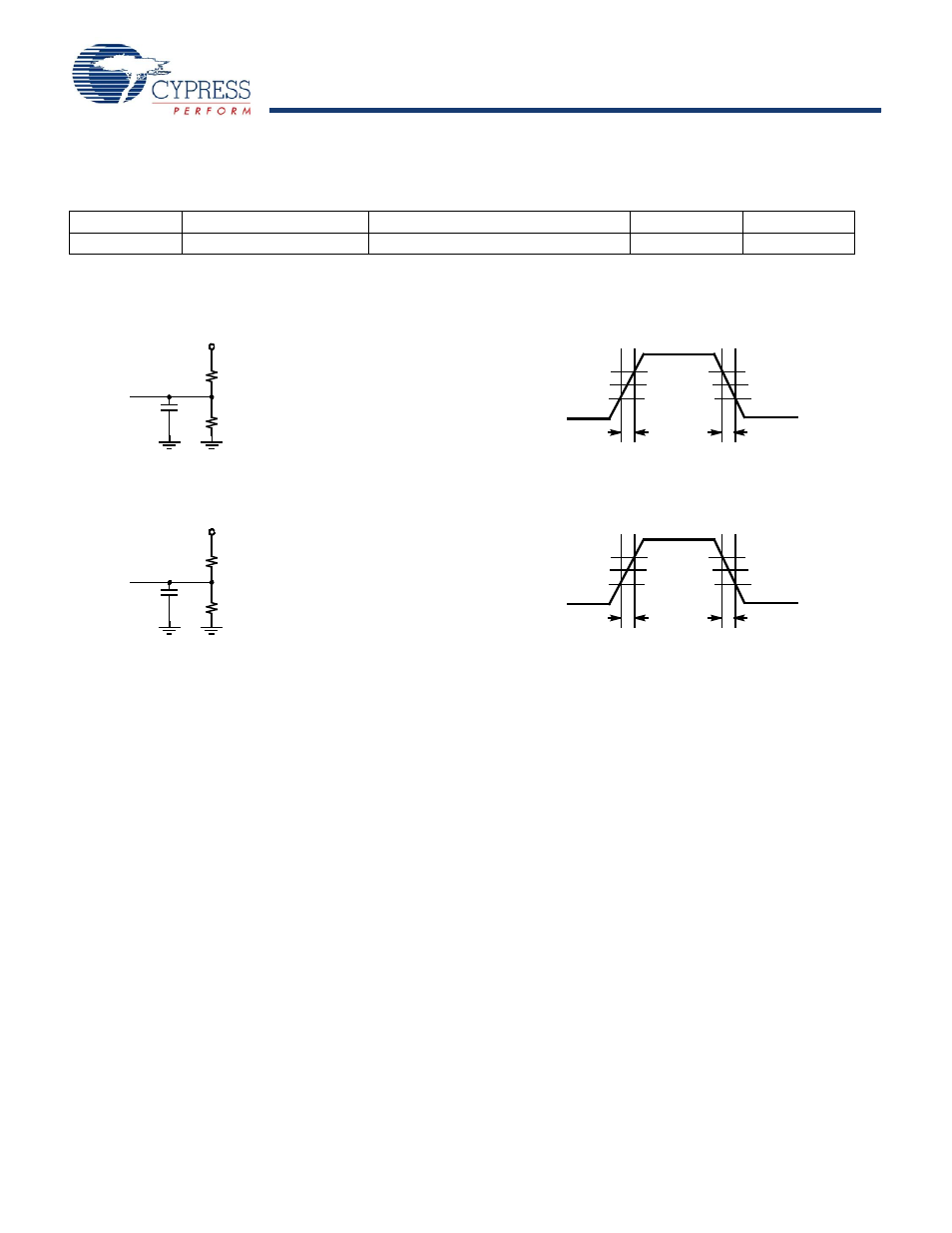
AC Test Loads and Waveforms
TTL AC Test Load (CY7B991)
TTL Input Test Waveform (CY7B991)
5V
R1
R2
C
L
R1
R2
C
L
CMOS AC Test Load (CY7B992)
3.0V
2.0V
V
th
=1.5V
0.8V
0.0V
≤1ns
≤1ns
2.0V
0.8V
V
th
=1.5V
80%
V
th
= V
CC
/2
20%
0.0V
≤3ns
≤3ns
80%
20%
V
th
= V
CC
/2
CMOS Input Test Waveform (CY7B992)
V
CC
R1=130
R2=91
C
L
= 50 pF (C
L
=30 pF for –2 and –5 devices)
(Includes fixture and probe capacitance)
R1=100
R2=100
C
L
= 50 pF (C
L
(Includes fixture and probe capacitance)
V
CC
=30 pF for –2 and –5 devices)
This manual is related to the following products: