Cleaning, service, and maintenance cleaning, Connection cord/plug assembly replace- ment – Carrier 30GT-911---062 User Manual
Page 12
Manufacturer reserves the right to discontinue, or change at any time, specifications or designs without notice and without incurring obligations.
Catalog No. 533-00078
Printed in U.S.A.
Form 30/48/50-6SI
Pg 12
10-06
Replaces: 30G,H,R-1SI
Book 1
1
2
4
4
Tab
1a 1b 5c 6a 6b
Copyright 2006 Carrier Corporation
CLEANING, SERVICE, AND MAINTENANCE
Cleaning —
The Navigator™ module can be cleaned with
a mild detergent. Isopropyl alcohol or a glass cleaner can be
used on all Navigator module surfaces.
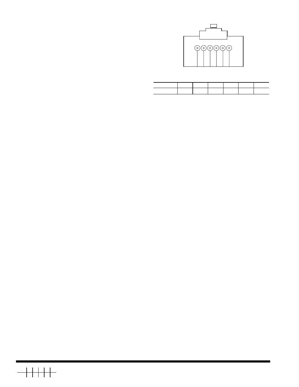
Connection Cord/Plug Assembly Replace-
ment —
If the RJ14 plug is damaged, it can be replaced. If it
is replaced, the wiring to the plug must be identical to the origi-
nal plug. Use Fig. 10 to record wire color. The wire sequence
should be the same for both ends of the cable as shown in
Fig. 10.
The connection cable (P/N 912-990010-2) can be replaced
if damaged. Replacement cables are available from
Replacement Components Division. Remove the Navigator
module from the LEN connection before proceeding.
1. Remove the 6 screws from the back of the case to gain
access to the internal plug for the device, and keep
them for installation later.
2. The back cover is connected to the touch pad by a ribbon
cable. The ribbon cable is not long enough to allow the
two halves to be completely separated. To be able to ac-
cess the plug connection, slightly offset the back cover.
Be careful not to damage the ribbon cable.
3. Unplug the damaged cable.
4. Plug in the new cable.
5. Insert the rubber grommet (included with new cable as-
sembly) into the cable entrance hole.
6. Realign the two halves of the Navigator module. Be sure
that the grommet is properly seated in the cable entrance
hole.
7. Reinstall the 6 screws previously removed.
NOTE: Failure to properly seal the Navigator module with the
screws and grommet will compromise the watertight integrity
of the device.
PIN
1
2
3
4
5
6
TAB
Fig. 10 — Pin/Plug Assembly
PIN
1
2
3
4
5
6
Wire Color