2 illustration of encoder data within master – Baumer GXP6H User Manual
Page 4
Manual_GXP6H_EN.doc
4/13
Baumer IVO GmbH & Co. KG
04.05.11
Villingen-Schwenningen,
Germany
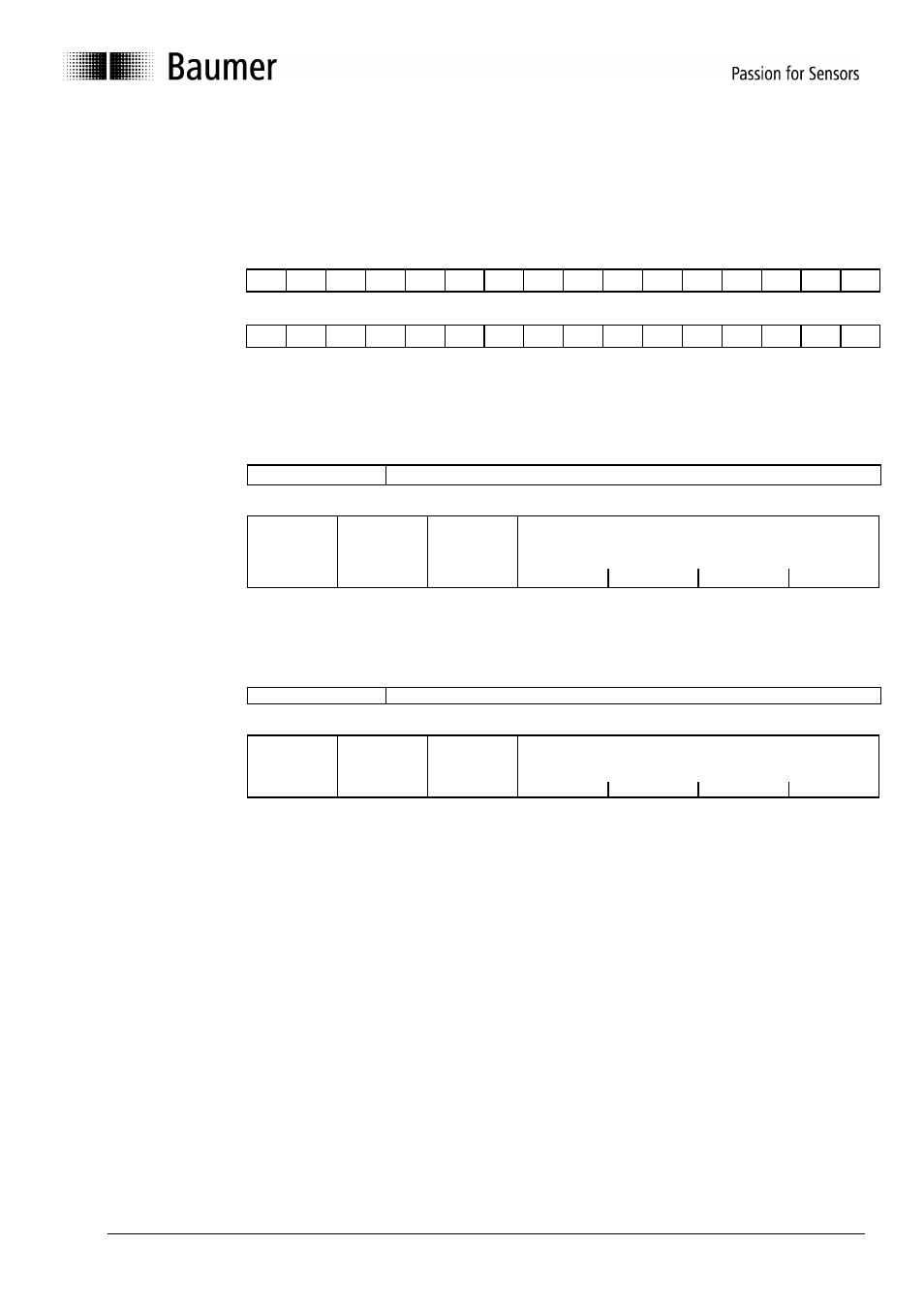
2 Illustration of Encoder Data within Master
The IN as well as OUT data of the encoder are assigned 2-word addresses within the master (control). The absolute
position of these word addresses depends on the position of the encoder on the Interbus ring.
2.1 Position of the Encoder Data within the 2-word Addresses
Please find below the value of the encoder data relating to the relative word address.
Word 0 (Byte 0,1) 2
31
2
30
2
29
2
28
2
27
2
26
2
25
2
24
2
23
2
22
2
21
2
20
2
19
2
18
2
17
2
16
MSB
LSB
Word 1 (Byte 2,3) 2
15
2
14
2
13
2
12
2
11
2
10
2
9
2
8
2
7
2
6
2
5
2
4
2
3
2
2
2
1
2
0
MSB
LSB
2.2 Significance of the OUT Data (Data from the Master to the Encoder)
D31
D25
D24 D0
OUT Data: Control word
Parameter
Control
word:
Enable
operation
Set zero
offset
Specific to
manufacturer
Parameter No.
D31 D30 D29 D28 D27 D26 D25
2.3 Significance of the IN Data (Data from Encoder to Master)
D31
D25
D24
D0
IN Data:
Status word
Actual position value or disturbance number
Status
word:
Actual
position value
not valid
Parameterizat
ion
Specific to
manufacturer
Disturbance number in case of error
otherwise 0000
D31 D30 D29 D28 D27 D26 D25