Maximum temperatures – Chromalox PN403-1 User Manual
Page 4
4
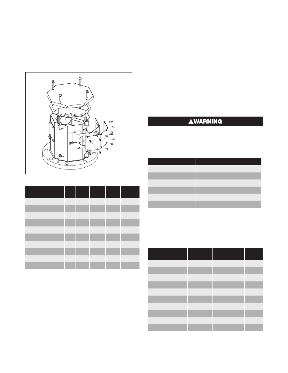
When reinstalling, be sure to properly align gasket, if
applicable, and tighten to 40-50 in/lbs.
Tip for Reinstalling Gaskets:
Place allen head screws through metal covers and
gentle push gasket hole over the threaded screw. This
will allow the gasket to stay in place while tightening
the cover.
Table A – E4 Wiring Information
Heater
kW Volts Phase
Total
Amps Circuits
LTFX-125-004E4
4
480
3
4.8
1
LTFX-128-008E4
8
480
3
9.6
1
LTFX-1212-012E4
12
480
3
14.5
1
LTFX-2212-024E4
24
480
3
28.9
1
LTFX-3212-036E4
36
480
3
43.4
1
LTFX-2325-060E4
60
480
3
72.3
1
LTFX-3325-090E4
90
480
3
108.4
3
LTFX-4325-120E4
120
480
3
144.5
2
LTFX-6325-180E4
180
480
3
216.8
3
LTFX-8325-240E4
240
480
3
289.0
4
Wiring Entrance Locations - Explosion
Resistant Housing Only (E2 Option)
The Explosion Resistant (E2) Housing features dedi-
cated conduit connection sizes and locations for either
NPT installation of conduit or Metric cable glands. In-
coming wiring must be suitable for a maximum termi-
nal enclosure temperature of 158˚F (70˚C). Wiring in-
stallation must be in accordance with Hazardous Area
requirements. The use of EYS seals or rigid conduit
may be required. Please consult with the local inspec-
tion authority.
Maximum Temperatures
Safe operation in a hazardous location requires the
maximum operating temperatures of all exposed sur-
faces of the heater including temperatures on the out-
side of the vessel, piping, flanges, screw plugs, enclo-
sures and other heat conducting parts be limited. The
flammable liquids, vapors or gases present determine
the maximum surface temperature permitted in any
hazardous location. The end user or purchaser of the
electric heating equipment is responsible for determin-
ing the proper classification of an area and for provid-
ing Chromalox with hazardous area specifications and
requirements for proper equipment design. (NEC and
IEC provide guidelines for evaluating and classifying
hazardous locations.)
An approved liquid level control or overtemper-
ature control must be installed to deenergize
the heater if the liquid level drops below the
top of the heater.
Maximum fluid temperature per following table:
Temperature Class
Maximum Fluid Temperature
T1 (450˚C)
440˚C
T2 (300˚C)
290˚C
T3 (200˚C)
195˚C
T4 (135˚C)
130˚C
T5 (100˚C)
95˚C
T6 (85˚C)
80˚C
The external surfaces of the heater must not exceed
the marked fluid temperature. An over-temperature
control should be used if there is a possibility of the
heater’s external surface temperature exceeding the
fluid temperature.
Table B – E2 Wiring Information
Heater
kW Volts Phase
Total
Amps Circuits
LTFX-125-004E2
4
480
3
4.8
1
LTFX-128-008E2
8
480
3
9.6
1
LTFX-1212-012E2
12
480
3
14.5
1
LTFX-3210-024E2
24
480
3
28.9
1
LTFX-3215-036E2
36
480
3
43.4
1
LTFX-3225-060E2
60
480
3
72.3
1
LTFX-4225-090E2
90
480
3
108.4
2
LTFX-8215-120E2
120
480
3
144.5
2
LTFX-9220-180E2
180
480
3
216.8
3
LTFX-12225-240E2 240
480
3
289.0
4