Wiring – Chromalox PN403-1 User Manual
Page 3
3
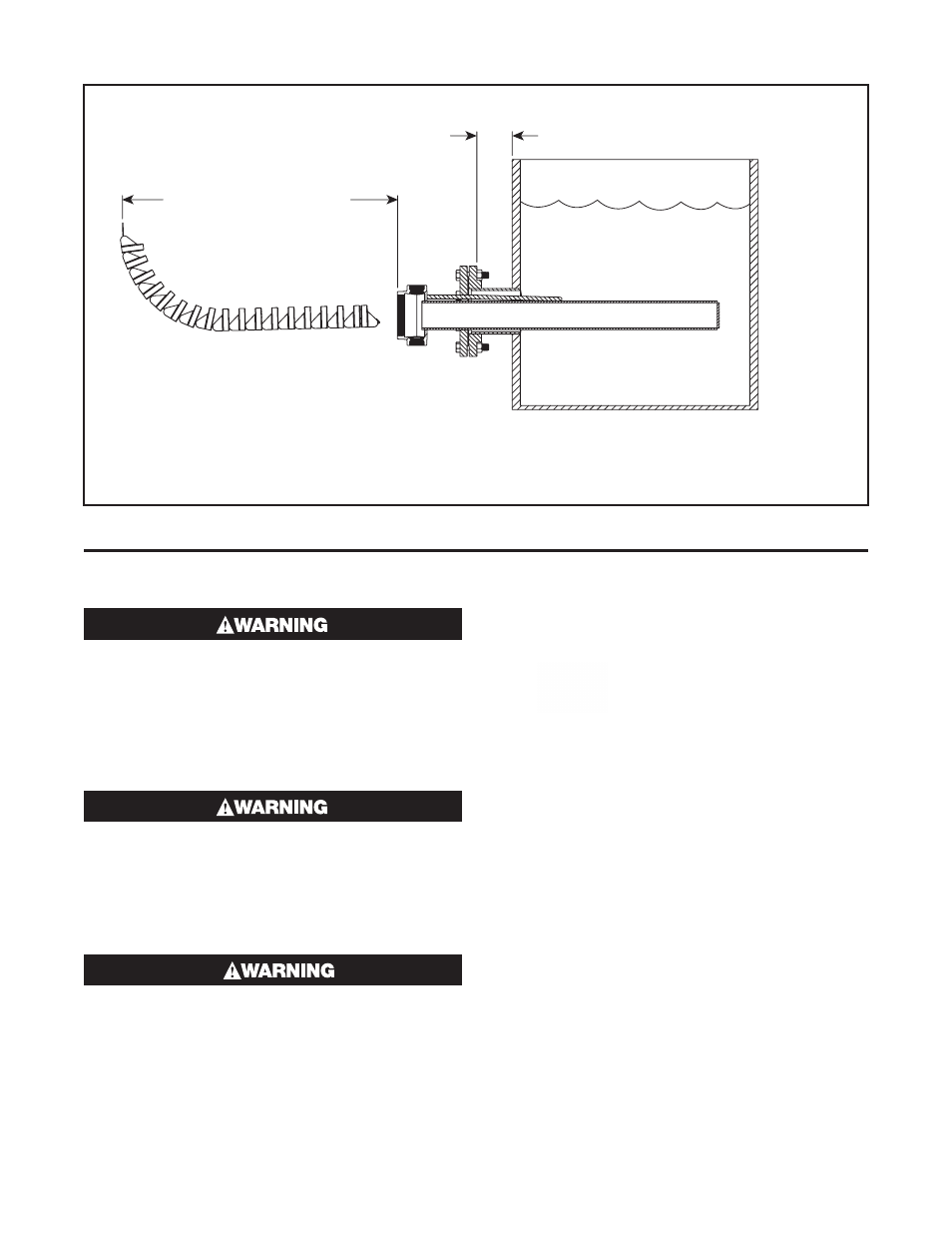
Allow for Tank
Insulation and Bolting
36” Min. Element
Removal Distance
Model LTFX
Fluid
Level
Open-Coil Elements
Figure 1
Wiring
ELECTRIC SHOCK HAZARD. Disconnect all
power before installing or servicing heater.
Failure to do so could result in personal injury
or property damage. Heater must be installed
or serviced by a qualified person in accordance
with applicable National Electric Codes, NFPA
70 and/or International Electric codes.
ELECTRIC SHOCK HAZARD. Any installation
involving electric heaters must be performed
by a qualified person and must be effectively
grounded in accordance with applicable Na-
tional Electric Codes and/or International Elec-
tric Codes to eliminate shock hazard.
The system designer is responsible for the
safety of this equipment and should install ad-
equate back-up controls and safety devices
with their electric heating equipment. Where
the consequences of failure could result in per-
sonal injury or property damage, back-up con-
trols are essential.
1. Electrical wiring to heating elements must be sized
and installed in accordance with applicable National
Electric Codes, International Electric Codes and/or
and applicable local codes by a qualified person as
defined by the code.
2. Temperatures at the heater terminals will require the
use of manganese nickel or equivalent temperature
lead wire. (Type TGS, TGT, or TGGT are recom-
mended.)
Wiring Entrance Locations - Moisture
Resistant Housing Only (E4 Option)
The Moisture Resistant (E4) Housing offers several
convenient options for conduit wiring & location. The
housing is equipped with two removable service en-
trance plates for installation of wiring. Any or all of the
six sides can be used for wiring locations. Refer to ex-
ploded view drawing. The housing can also be rotated
(by removal from flange) to allow for more position
possibilities. To install service entrance holes, simply
remove the side Allen screws and use the centering
depression to drill the appropriate size hole. Reinstall
the gasket(s), if applicable, and service entrance plates
by tightening the Allen head screws to 4-5 in/lbs. The
‘Octobox’ style of housing can be removed for ease of
access to element bussing or to better locate the pow-
er conduit(s) entry point. To accomplish, simply remove
the Allen-head screws on the outside of the housing.