A. b. c, B1. b2, Tube holder configurations – Drucker Diagnostics Model 642VFD Plus Centrifuge User Manual
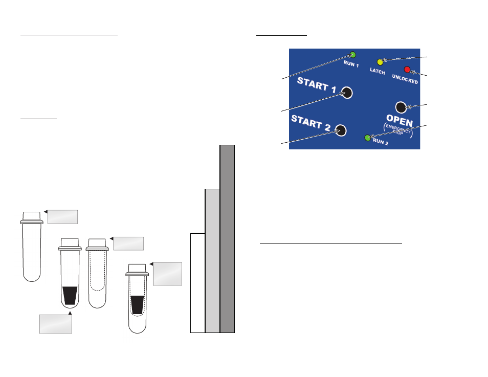
Page 5: Control panel
Page 5
Page 8
* This part is available as an accessory. Contact The Drucker Company for assistance.
A.
B.
C.
Tube Holder Configurations
The
642VFD-Plus
is capable of spinning test tubes up to 17 mm x 100 mm with its
horizontal rotor. Use the following chart and drawing to determine which tube holder
and cushion combination should be used with your application.
1. Opposing tube holders must be identical.
2. Opposing tube holders must be empty or loaded with equally weighted samples.
3. If an odd number of samples is to be spun, use a water-filled tube with the unpaired one.
Your centrifuge must contain a balanced load in order to work properly.
To ensure that the load is balanced, keep these rules in mind when
inserting test tube samples into the six position horizontal rotor:
DirecTions:
1. Compare the tube to be spun with the boxes shown here.
2. Find the box that most closely matches the tube’s length.
NOTE: The tube length with its stopper or cap must be shorter
than the chosen box.
3. Match the letter from the chosen box with one of the configurations
shown. For Example: A tube as long as box B. Accordingly, we
can use a 100 mm tube holder with a 1525 cushion or a 75
mm tube holder with no cushion, .(configurations B1 or B2).
A.
100 mm
Tube Holder
RED
100 mm Tube
Holder with
1525 cushion
75 mm
Tube Holder
B1.
B2.
RED
GREEN
C.
75 mm Tube
Holder
with 1525
cushion
GREEN
‘START 1’
Lights up when the machine is operating for a 10
minute run. Power is being applied to the motor.
‘START 1’
Lights up when the machine is operating for a 5
minute run. Power is being applied to the motor.
‘OPEN / STOP’
Allows for access into the rotor chamber by dis-
engaging the locking mechanism. Entry is only
permitted when the rotor is stopped. Pressing this
button during operation will terminate the run and
unlock the lid after the rotor has come to a stop.
‘START 1’
Begins a new 10 minute run.
NOTE: The lid must be closed.
‘START 2’
Begins a new 5 minute run.
NOTE: The lid must be closed.
‘LATCH’
Lights up when the lid has been closed properly.
‘UNLOCKED’
Lights up to indicate that the locking mechanism
has been deactivated, allowing access to the rotor
chamber.
‘RUN 1’
Indicator
Light
‘RUN 2’
Indicator
Light
‘LATCH’
Indicator
Light
‘UNLOCKED’
Indicator
Light
‘OPEN / STOP’
Button
‘START 1’
Button
‘START 2’
Button
Control Panel:
To verify the preset run time, RPM and brake settings:
1. Plug in the line cord.
2. Press the OPEN button to unlock the lid.
3. Open the lid.
4. Press and hold a START button until the latched light begins to flash, then
release.
5. The unit will indicate the settings for the START button you selected with
audible “beeps”. Count the number of beeps, they indicate the run-time set-
ting in minutes.
6. Press the same START button again, count the beeps, this time they indi-
cate the RPM setting (one beep = 100 RPM).
7. Press the START button again counting the beeps, they indicate the brake
setting magnitude (1=off, 10=Maximum).
8. Press STOP/OPEN to return to the idle state.
9. If you have a two speed model, you can check the second preset run time,
RPM and brake settings by using the second START button.