Maintenance 8” models, cont, Impellar and flow tube assemblies, Inlet spider – Baseline Systems BHM Series Hydrometer User Manual
Page 38
38
• Hydrometers Operation and Maintenance Manual
Maintenance 8” Models, Cont.
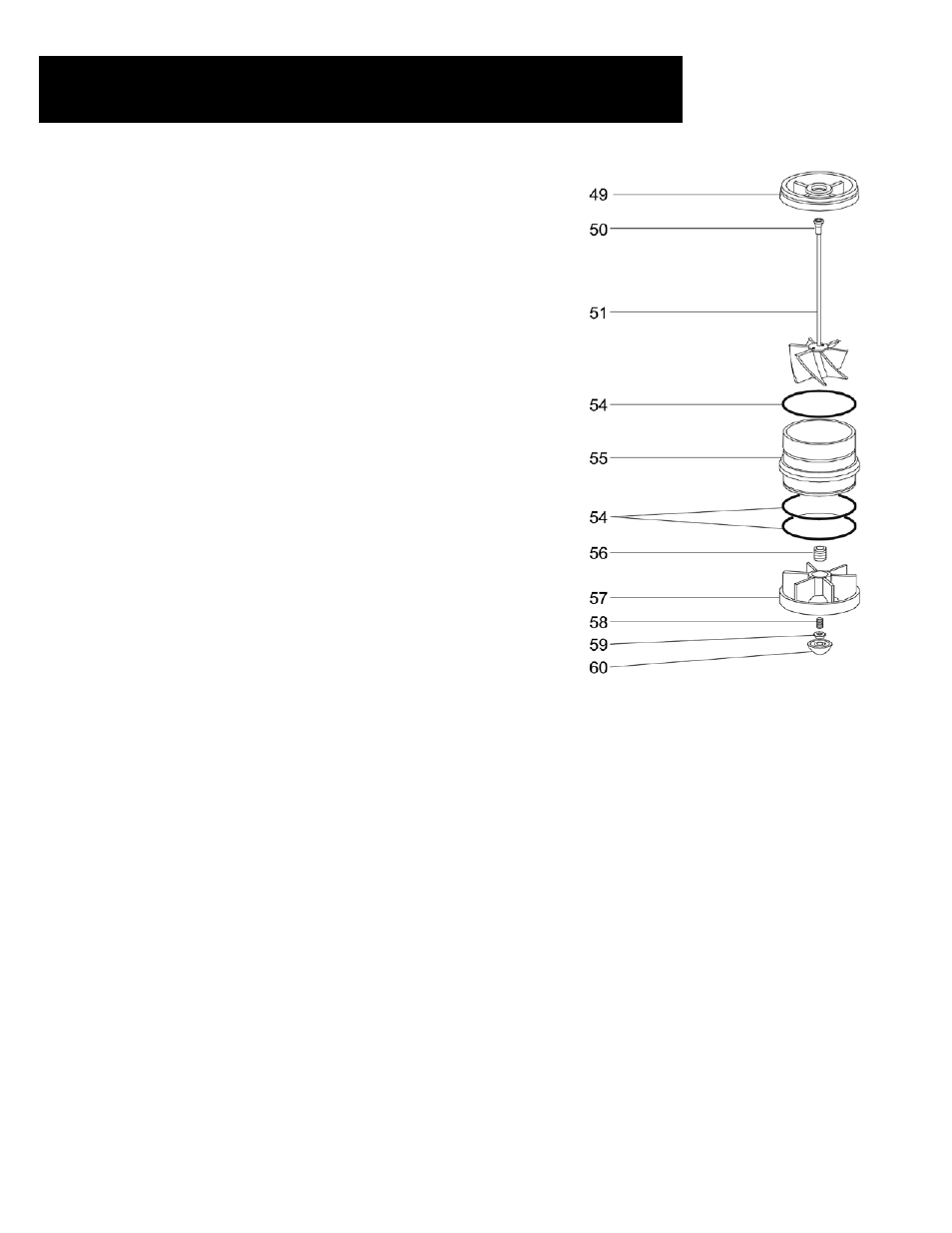
IMPELLAR AND FLOW TUBE ASSEMBLIES
Dis-assembly
• Remove valve seat base (49) from atop the flow tube (55). Be careful not
to damage the impeller shaft. Inspect the valve seat base for excessive
wear and replace as necessary.
• Remove the impeller (50).
• Inspect for cracks or excessive wear and check that the impeller shaft is
perfectly straight. Replace if necessary.
• Remove the flow tube (55).
• Inspect and replace as necessary.
• Inspect the upper and lower flow tube o-rings (54) and replace as
necessary.
• Remove the inlet spider (57) assembly. Inspect and repair as necessary.
Re-assembly
• Replace the inlet spider assembly (57) into the hydrometer body.
• Place the two lower flow tube o-rings (54) onto the flow tube (55).
• Place the upper flow tube o-ring (54) into the valve seat base (49).
• Replace the flow tube (55) atop the inlet spider assembly (57) in the
hydrometer body.
• Replace the impeller assembly (51) into the flow tube (55) - the impeller
shaft should rest in the lower bearing bushing (56).
• Place the valve seat base (49) over the impeller shaft so that it rests atop
the flow tube (55).
INLET SPIDER
Dis-assembly
• Unscrew and remove the cap (60). Inspect and replace as necessary.
• Remove the lock nut (59).
• Unscrew and remove the lower bearing screw (58) from the inlet spider
(57). Inspect and replace as necessary
• Inspect the inlet spider (57) and the lower bearing bushing (56) and
replace as necessary.
Re-assembly
• Screw the upper bearing bushing (56) back into the top of the inlet
spider (57).
• Replace the lower bearing screw (58) into bottom of the inlet spider.
Tighten approximately eight turns.
• Replace the lock nut (59) and the cap (60).