Baseline Systems BL-5200R Powered biCoder User Manual
Baseline Systems Measuring instruments
BL-5200R Series Powered biCoder™
Installation Guide
1-866-294-5847
Rev 11.5.2012
www.baselinesystems.com
Each terminal of the Baseline’s Powered biCoder has a serial number which is used as an
address to identify it to the BaseStation controller. The BaseStation broadcasts a message
along the two-wire and the biCoder responds by turning the attached valve on or off.
Powered biCoder Installation Instructions
1. Copy the programming information from your old clock. Use the worksheet found in the
appendix of your controller user manual to make this process easier.
2. After you have finished copying the programming information, disconnect valve wires (one
at a time) from your clock, making sure to indicate which wire belongs to which zone.
(Masking tape works well for this.)
3. Connect the valve wires to the valve terminals on the Powered biCoder, writing down
which valve and zone is being attached to which terminal.
Note: Wire connections must be DBR/Y or equivalent moisture-resistant connectors. Install all
connections according to the manufacturer’s instructions.
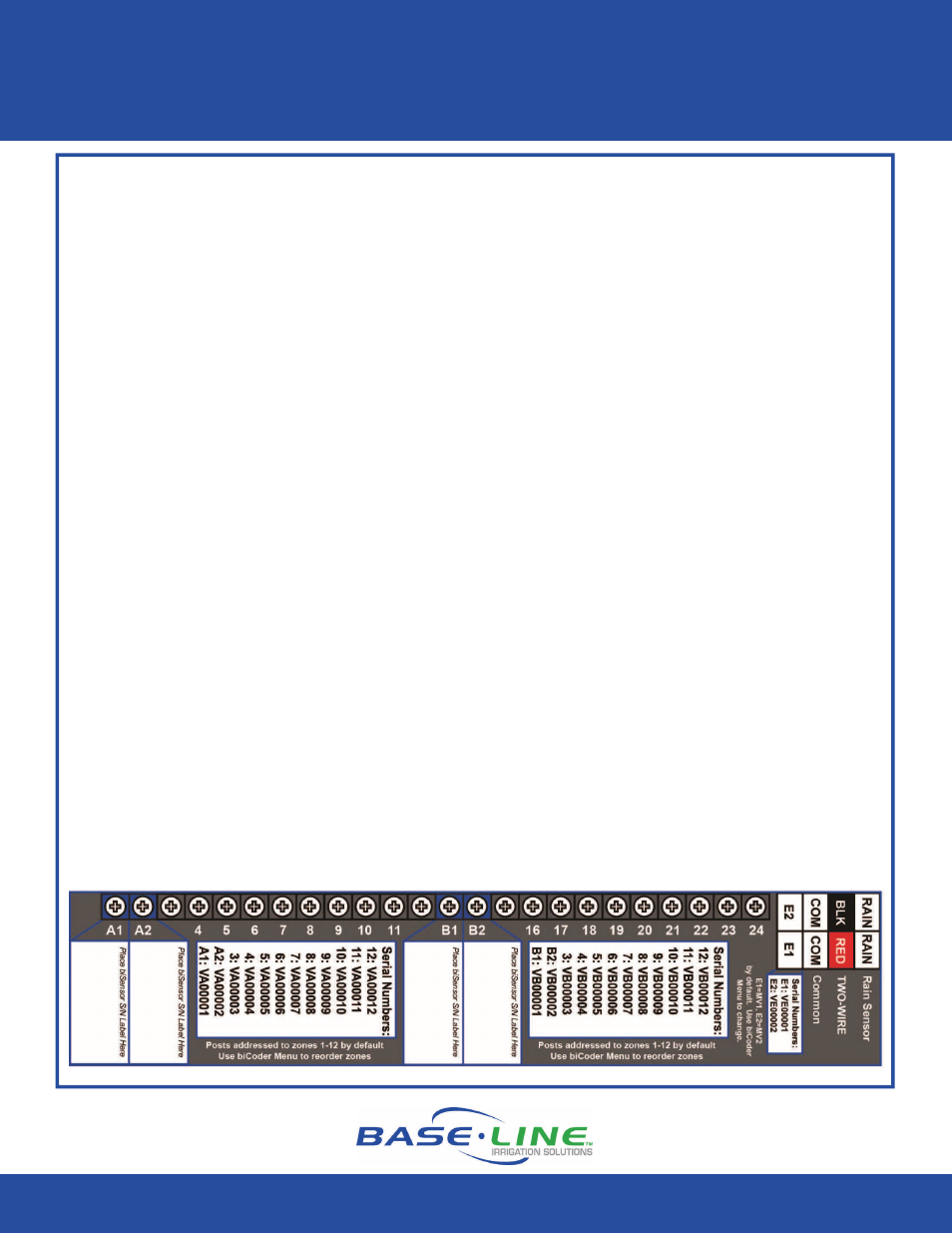
4. If you are using biSensors, connect the valve wiring for the zones where the sensors are
located to terminals A1, A2, B1, or B2.
5. If you are using two-wire, connect it to the two-wire terminals.
6. Configure your system according to the configuration section in your controller user
manual.
7. Power up the controller and verify that the LEDs on the front panel are lit.
BL5224 24 Valve Powered biCoder (The 12 Valve Powered biCoder has only A1 - A12 terminals
populated. The 36 & 48 Valve Powered biCoder incorporates a second BL5224 PCA.)