Baseline Systems BaseStation 3200 in X Cabinet User Manual
Page 7
Installation and User Guide for Baseline Cell Modems in X and XS Cabinets
Page 3
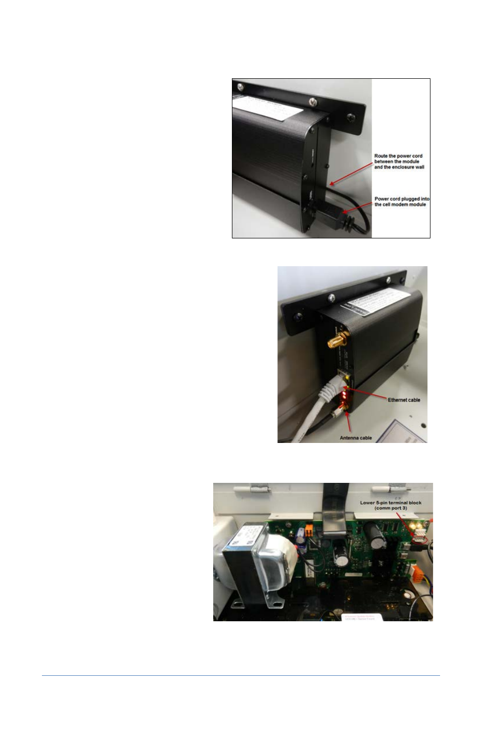
11. Plug the power cord into the cell
modem module as shown in Figure 4.
12. Plug the Ethernet cable into the
Ethernet jack on the cell modem
module as shown in Figure 5.
13. Attach the male SMA connector (small
end) on the antenna cable to the
connector on the cell modem module
labeled WWAN Main as shown in
Figure 5.
14. Align the holes on the cell modem
module with the standoffs on the
inside roof of the enclosure and use
the screws provided to secure the
board to the enclosure.
15. Thread the coax connector on the antenna cable
onto the stem of the antenna and hand-tighten it.
16. Plug the 5-pin connector from the cell modem
power cord into the rear 5-pin terminal block
(comm port 3) on right end of the controller board
as shown in Figure 6.
Note: If another connector is attached to the rear
5-pin terminal block, disconnect it, and then
reconnect it to the front 5-pin terminal block.
Figure 5
Figure 4
Figure 6