6installation – B&G H2000 Pilot *DISCONTINUED* User Manual
Page 7
Tank Level Sensing Processor and Sensors
Page 3
6
Installation
6.1
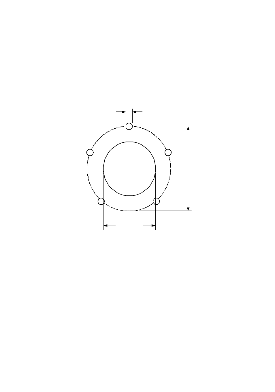
Installation of 5-Bolt Flange Fittings
Note: Minimum required distance is 55mm (2”) above tank surface to clear elbow
fittings/pipes.
Select a suitable position for the tank fitting(s), cut the required holes in accordance with the
following diagram
5mm
CLEARANCE
37mm
52mm
WARNING: THIS DIAGRAM IS NOT DRAWN TO SCALE.
Install the flange fitting as follows:
1. Determine the depth of the tank including the depth of any pump pick-up tubes (refer to the
diagram on Page 4 of this manual).
2. Cut the 7.5mm (¼ inch) diameter Nylon tube so that its cut end will be suspended
approximately 50mm (2 inches) above the tank pick-up tube.
Note: For tanks deeper than 0.9m (3 feet), the extension kit (supplied) will be required (refer
to the diagram on Page 4 of this manual).
3. Slide the weight over the cut-end of the Nylon tube then slide the collet cover under the
weight. Press the end of the Nylon tube into the union fitting. Snap the collet cover into
place to prevent the weight from detaching when immersed in the tank.
4. Place the gasket over the tank opening, between the flange and the tank, align the
asymmetrical bolt holes and attach the flange to the tank using the bolts supplied.
5. Connect the Swagelock tubing to the elbow on the flange fitting and tighten.
Note: For each side-tank installation an additional 90
o
elbow will be required (refer to the
diagram on Page 5 of this manual).