Tank level sensing processor and sensors, Warning: this diagram is not drawn to scale – B&G H2000 Pilot *DISCONTINUED* User Manual
Page 11
Tank Level Sensing Processor and Sensors
Page 7
6.5
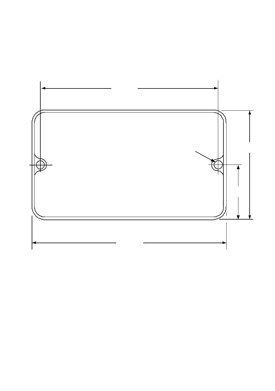
Installation of the Tank Level Sensing Processor
Select a suitable dry location and, using the dimensions from the template diagram below,
secure the processor unit with the screws supplied.
218mm
235mm
130mm
5.2mm
65mm
WARNING: THIS DIAGRAM IS NOT DRAWN TO SCALE