B&G HS2000 User Manual
Page 61
HS 2000 User Manual
Part 4 - Installation Information
HB-0846-03
4-12
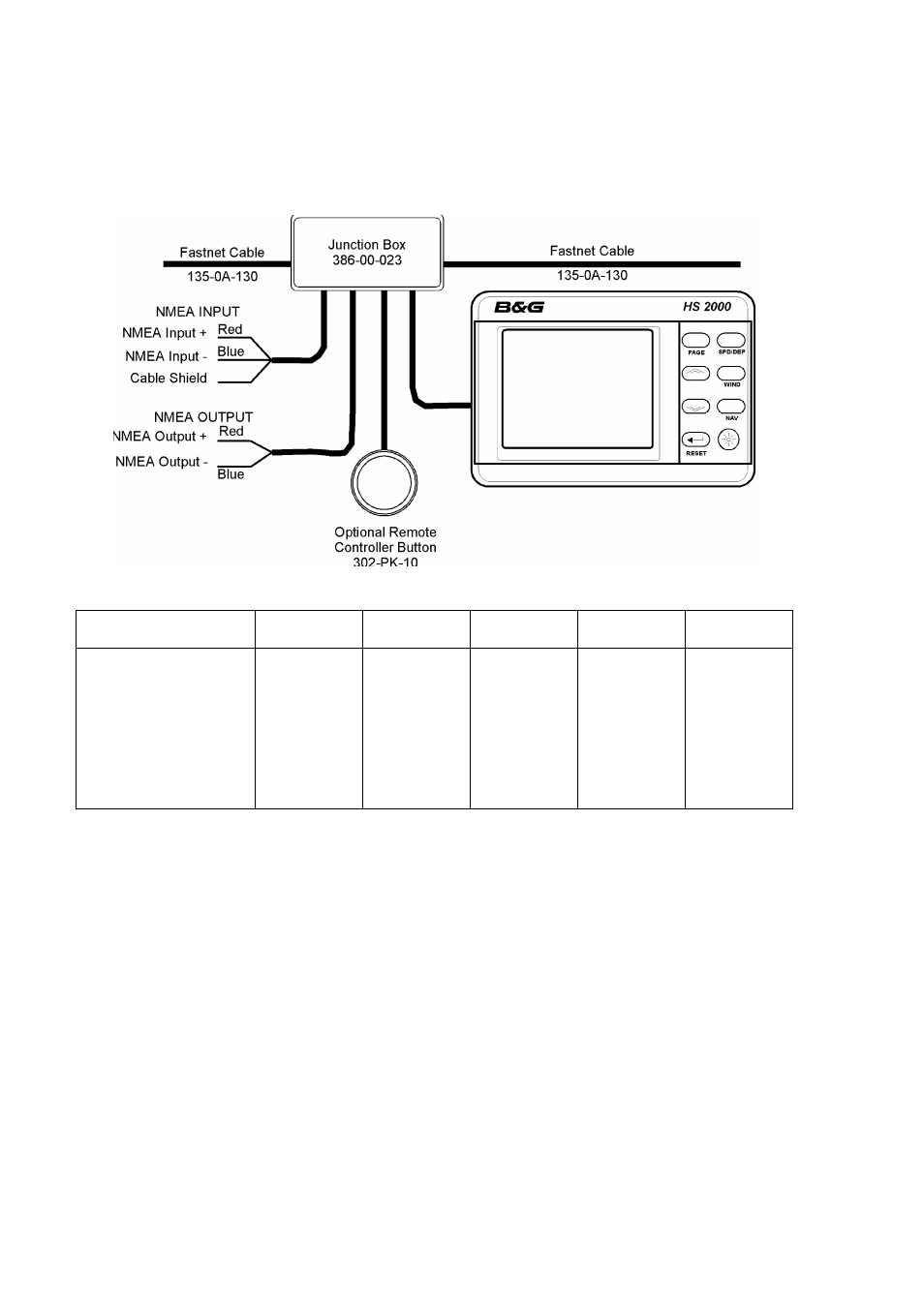
8-BUTTON NMEA FULL FUNCTION
DISPLAY INSTALLATION SHEET
INSTALLATION NOTES
??
An NMEA FFD can be connected at any point on the system network. Typically an NMEA
FFD is mounted close to the NMEA device, e.g. at the chart table next to the GPS, thus
minimising the NMEA cable routes.
??
NMEA FFD's can be used in combination with all other display types; i.e. standard FFD's,
Halcyon displays, 20/20 and Pilot displays.
SCREENED CABLES
??
Shielded NMEA cables are supplied to provide protection against unwanted emissions
(EMC) and must be connected in accordance with these instructions.
??
NMEA cable shields must be connected at the TRANSMITTING end.
??
The NMEA output cable shield should be connected to the other cable shields in the
junction box supplied.
NETWORK TERMINATION
??
If the NMEA FFD is the last unit on the system network a network terminator MUST be
fitted across the network data wires; i.e. between the green and white wires. Only two
network terminators are required per system.
NMEA FFD
CABLE FUNCTION
FFD CABLE
COLOUR
SYSTEM
NETWORK
NMEA
INPUT
NMEA
OUTPUT
REMOTE
BUTTON
Network Data -ve
Green
Green
-
-
-
Network Data +ve
White
White
-
-
-
Network Cable Shield
Shield
Shield
-
Shield
-
Ground
Black
Black
-
Blue
Blue
Supply +ve
Red
Red
-
-
-
NMEA Input Signal
Brown
-
Red
-
-
NMEA Input Return
Blue
-
Blue
-
-
NMEA Output Signal
Violet
-
-
Red
-
Remote Control Button
Yellow
-
-
-
Red