0 introduction, 0 controls & indicators – Aphex CX 500 User Manual
Page 4
Page 6
Page 7
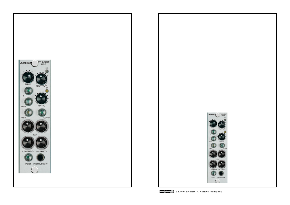
2.0 INTRODUCTION
The Project 500 is a 500 Series channel strip module that includes
a Class-A mic pre, an optical compressor and a two-band equal-
izer. The optocoupler was designed to be as fast as possible and is
produced exclusively for Aphex. The inputs and outputs are elec-
tronically balanced.
3.3 GAIN REDUCTION LED
The Gain Reduction LED provides visual feed- back as to the
amount of gain reduction. The LED will glow yellow when gain
reduction occurs. The brighter it glows, the more gain reduction
is taking place.
3.4 RATIO CONTROL
The Ratio knob controls the decibel relation- ship between the
amount of increase in input signal vs. the amount of increase
in output signal. All the way to the left, the output will increase
approximately 1dB for every 1.5dB increase in input, providing a
very light and smooth compression. All the way to the right, the
output will increase approximately 1dB for every 6dB increase in
input, providing a more heavily compressed sound.
3.5 POST BUTTON
The Post button determines if the compressor function comes
before or after the equalizer function. When the button is not
lighted the compressor comes before the equalizer. When the
button is lighted the compressor comes after the equalizer.
• Class-A mic pre design from the popular
Aphex Project Channel.
• The optical compressor is extremely trans-
parent and can be assigned to come before
or after the EQ.
• Two bands of semi-parametric EQ with
overlapping frequencies.
• 10Mohm instrument input.
• 48V phantom power, 75Hz HPF and Phase
reverse buttons are provided.
3.0 CONTROLS & INDICATORS
3.1 TRIM CONTROL
The Trim knob controls the amount of input
gain to the mic pre. The Signal LED will light
green when an input signal is detected. It will
turn yellow as the input signal increases and
will turn red when the input is being clipped.
3.2 COMPRESSOR ON/OFF BUTTON
The Compressor on/off button activates or
deactivates the compressor function.