0 controls & indicators, 2 simplified block diagram – Aphex EX BB 500 User Manual
Page 8
Page 8
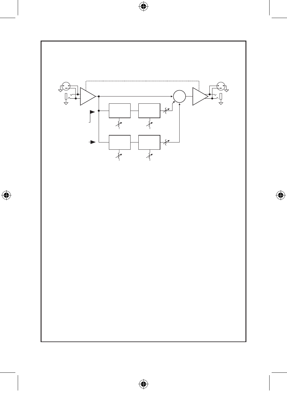
2.2 SIMPLIFIED BLOCK DIAGRAM
Active Balanced Inputs
XLR-3F
1/4” TRS
+4/-10 Operating Level Switch
Tunable
Highpass
Filter
Transient
Discriminate
Harmonics
Generator
Tunable
Lowpass
Filter
Phase &
Dynamics
Processor
Variable
Harmonics
Tune
600Hz-5kHz
Mix
Mix
SUM
Active Balanced Outputs
XLR-3M
1/4” TRS
Variable
Drive
Tune
50Hz-200Hz
Aural Exciter Sidechain
Big Bottom Sidechain
Effects are created through dynamic phase, frequency, and amplitude modification and recombination.
3.0 CONTROLS & INDICATORS
3.1 BIG BOTTOM DRIVE CONTROL & INDICATOR
This control allows you to adjust the input signal to optimum
levels required for Big Bottom to work effectively. To find the
optimum level, turn the control clockwise until the green LED at
the right of the Drive control pulses on the bass peaks. Longer
and brighter pulsation means a longer bass sustain is being cre-
ated. You will find a range of settings that yields very musical and
powerful bass.
Please note there are valid reasons for why the green LED may not
pulse by the time this control reaches 2 o’clock. The input signal
may be too low to trigger the Big Bottom processor. On the other
hand, if the green LED is pulsing strongly at settings as low as 9
or 10 o’clock, the input signal may be too hot. This can cause
overload distortion.
Additionally, the LED may not pulse when the incoming audio
does not have significant low frequency content.
NEW EXBB500 MANUAL.indd 8
1/12/12 3:31 PM