0 compression – Aphex COMP 500 User Manual
Page 5
Page 8
Page 9
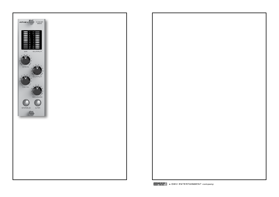
3.5 OUTPUT LEVEL CONTROL
This knob controls the overall output level of
the module and drives the output level meter.
3.6 OUTPUT LEVEL METER
This 10-sement meter provides visual feedback
of the output level of the device. The meter
range if from -20dBu to +3dBu.
4.0 COMPRESSION
It you are reading this, congratulations! Learning more about
what compression is and how it benefits you will ensure
you get the best results from your COMP 500 module.
COMPRESSORS-WHAT THEY DO
The basic idea is that a wide range of input levels is automatically
“compressed” into a smaller range of output levels. After compres-
sion, sounds that were low in volume are higher in volume
and sounds that were high in volume are made lower in volume.
This results in more consistent volume levels that sit “just right”
in a mix without some parts being too loud with other parts too
soft.
PUNCH AND SUSTAIN
When a compressor reduces the volume of a loud sound, it does
so in way that is unique to each type of compressor. The time
it takes for this volume reduction to occur is called “attack”. An
attack that is too fast can change the natural character of an
instrument while too slow can lose the benefits of compression.
The COMP 500s interactive attack adapts to the input signal,
controlling volume without changing character and enhancing
punch while retaining articulation.
Typically, compression creates more sustain by raising the level
as the sound decays. This is more or less apparent, depending on
the input signal.
3.7 ENABLE BUTTON
This is essentially a bypass for the device. When
the module is active this button will light up.
The light will go off when the unit is bypassed.
3.8 LINK BUTTON
Two COMP 500 modules can be stereo linked
when they are installed as adjacent odd/even
pairs. Slot 1 & 2, 3 & 4, etc. This follows API’s
protocol for linking. Frames made by other
manufacturers may be different. Check your
frames’ manual for details on stereo linking.
Engaging the LINK button on both modules
will cause the module with the most gain reduc-
tion to be the master and the same amount of
gain reduction will be applied to the adjacent
module. This feature helps maintain a wide
stereo image. The Drive and Output param-
eters must be set so that the gain structure is
the same on both modules for this function to
work properly. Pin 6 of the modules are used
for this function.