Install wing inside drags – Great Plains FH6800HD Predelivery Manual User Manual
Page 29
Great Plains Manufacturing, Inc.
Assembly
25
01/14/2014
564-070Q
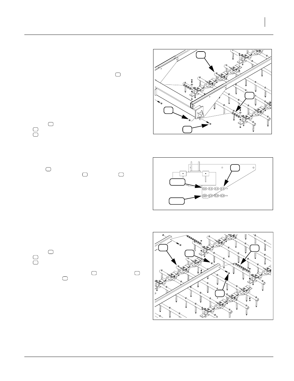
Install Wing Inside Drags
Refer to Figure 26 and Figure 21 on page 21
73. Identify the drags to use on the inside of each wing.
These are always the widest of remaining sections.
If any of these drags has a side chain (
in
Figure 21 on page 21), place it so that the chain is to
wing center.
74. Lay two of this size drag out flat either side of the
center wing width.
75. Back the implement up to the drags. Raise the arms
up. Leave the wings unfolded.
76. Remove fasteners from free ends of leading
chains
:
802-722C HHCS 9/16-12X3 1/2 GR5 ZNYCR
803-319C NUT HEX TOP LOCK 9/16-12 ZNYCR
Refer to Figure 27
77. For the standard 40
° tooth angle secure each
chain
to the lower holes in the mount (between
the plates), using bolts
and lock nuts
. Tighten
nuts only to Grade 2 torque specification.
For the alternate 22
° tooth angle, use the upper
holes. Using 22
° also requires chain relocation. See
Tooth Angle in “Operator’s Manual” for details.
Refer to Figure 28
78. Lower the arms.
79. Remove fasteners from free ends of trailing
chains
:
802-024C HHCS 3/8-16X3 GR5
803-013C NUT LOCK 3/8-16 PLT
Secure free ends of chains
to arm with bolts
and lock nuts
. Tighten nuts only to Grade 2
torque specification.
If this is a model FH6400 harrow, 12-row drag installation
is complete. Continue at “Install 4-Row Drag Exten-
sions” on page 28.
Figure 26: Wing Inside:
Attach Leading Chain
31648
60
5
51
30
31
30
51
60
Figure 27: Wing Inside:
Leading Chain Mount Holes
31756
30
22
°
40
°
30
51
60
Figure 28: Wing Inside:
Attach Trailing Chain
31648
53
5
39
29
29
39
53
29
39
53