Wing frame – Great Plains FH6800HD Predelivery Manual User Manual
Page 13
Great Plains Manufacturing, Inc.
Assembly
9
01/14/2014
564-070Q
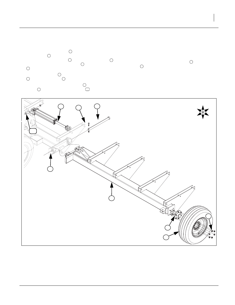
Wing Frame
11. Remove 1/2 x 2 hex bolts
and 1/2 lock nut from 1/2
x 20 3/4 pin
on both ends of center frame. Attach
LH and RH wing frames
, to center wing frame
,
re-install the 1 1/2 x 20 3/4 pins
, 1/2 x 2 hex bolts
and 1/2 lock nuts to secure.
12. Attach tire/wheels
to 6-bolt hub/spindle assembly
with 9/16 lug nuts
.
13. Attach base end of fold cylinders
to center wing
frame
, secure with 1 x 3 1/8 pin
, 1.5 x 1.00
x.075 machine washers and 3/16 x 2 cotter pins.
Bend cotter pins over to secure.
14. Do not hook up rod end of cylinders
to center wing
frame
until hydraulics are completely hooked up
and purge of air. See hydraulic pages 10-12 for
details.
15. Tighten all bolts with lock nuts snug, but do not
torque. The rest of bolts may be tightened to specs,
See “Torque Values Chart” on page 31.
4
3
1
2
3
4
7
8
7
9
2
10
9
1
Figure 7
Wing Frame
42995
2
3
U
D
F
B
L
R
8
9
1
4
7
6
10