Hose handles, Purging hydraulic system, Hose handles purging hydraulic system – Great Plains DVN8552 Assembly Manual User Manual
Page 40
36
8321-8552DV
Great Plains Manufacturing, Inc.
550-353Q-ENG
02/12/2014
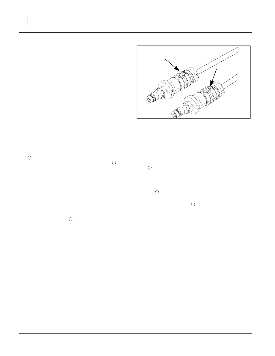
Hose Handles
Refer to Figure 38
186.To distinguish hoses on the same hydraulic circuit,
refer to hose handles. The hose under an extended-
cylinder symbol feeds a cylinder base end. The hose
under a retracted-cylinder symbol feeds a cylinder rod
end.
187.Once all hoses are tightened, hook hoses to tractor
Purging Hydraulic System
188.Charge the lift system first. Extend the lift cylinders
(black handles) until the center section is fully
raise. Remove the cylinder transport locks
. The
wings will not start to rise until the center cylinders
are fully extended and the master cylinders begin to
bypass oil through the rephasing ports, to the wing
cylinders. Watch for leaks and retighten fittings if
necessary. Continue to pump oil to the lift system
until the wing cylinders are also fully extended. At
this point, reverse the flow and lower the unit to the
ground, retracting all cylinders. Raise and lower the
unit several times to purge air from the system.
189.You may now charge the fold system. Before charg-
ing the fold cylinders
, make sure the rod end of the
cylinders are un pinned and block is under cylinder
as shown, so that when the rod is extended, it will
clear the wing fold brackets. Extend the fold cylinders
(green ends) completely and then close them.
Extend and retract the cylinders several times to
purge air from the system. Now the cylinders may be
extended far enough to be connected to the wing fold
brackets. Remove wood block and install 1 x 3 11/16
pin
, 1.5 x 1.0 x.075 machine washer and 3/16 x 2
cotter pin.
190. The gang lift system
(red handles), will need
purged like the lift system. Raise and lower the gang
system several times to purge air from system.
Figure 38
Hose Handles
41552
1
2
3
3
4
5