Install hydraulic valves – Great Plains DVN8552 Assembly Manual User Manual
Page 36
32
8321-8552DV
Great Plains Manufacturing, Inc.
550-353Q-ENG
02/12/2014
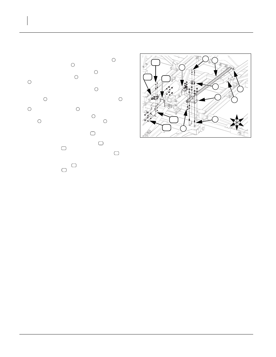
Install Hydraulic Valves
Refer to Figure 32
164.Attach depth stop valve mounting bracket
with 5/8 x
3 1/32 x 5 1/2 u-bolts
, 5/8 lock washers and 5/8 nuts.
165.Align holes in depth control valve
to top of depth stop
valve mounting bracket
using 5/16 x 2 Gr. 5 hex bolts
and 5/16 lock washers.
166.Slide one end of depth stop tube
(with 2 holes)
through slotted hole in depth stop valve mounting
bracket
. Slide other end of depth stop tube
over
peg on left side of level bar, secure with 1/2 flat washer
and 1/8 x 1 cotter pin
.
167.Bolt depth stop screw assembly
to front of depth stop
tube
with 1/2 x 2 1/2 Gr. 5 hex bolts
, 1/2 lock wash-
ers and 1/2 nuts.
168.Align holes of rebound bracket
on front side of cen-
ter frame tube (to right of level bar mount assembly.
Align holes in rebound mount plate
with holes on
rebound bracket
(back side of side of center frame
tube, secure with 1/2 x 4 1/2 Gr. 5 hex bolts
, 1/2 lock
washers and 1/2 nuts.
169.Mount rebound valve
in position shown, with 5/16 x
4 Gr. 5 hex bolts
, 5/16 lock washers and 5/16 nuts.
170.Tighten rest of bolts to specs, See “Torque Values
Chart” on page 43 and bend cotter pin.
171.Install all hydraulic fittings as shown in steps below.
Figure 32
Hydraulic Valves
41659
8
14
1
5
6
4
2
7
4
3
10
12
11
13
U
D
F
B
L
R
1
2
3
1
4
5
1
5
6
7
8
5
9
10
11
10
12
13
14