Install orifice plates, Row shutoff, Install orifice plates row shutoff – Great Plains YP4025F-1670 Material Rate User Manual
Page 49
Great Plains Manufacturing, Inc.
Fertilizer Rate
47
2014-03-13
401-571B
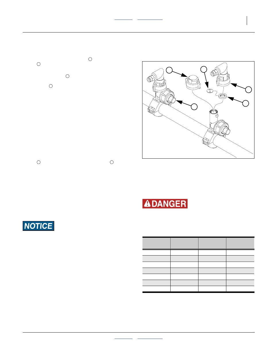
Install Orifice Plates
Refer to Figure 13
Insert the plate inside the gasket
supplied with the
nozzle
. Insert the gasketed plate with the legend side
facing out the nozzle outlet (typically up).
In general, the orifice
needs to be small enough to
create enough pressure in the manifold to operate the
check valves
in the boom clamps, but not so much that
the system dumps product at the boom relief valve.
The recommend operating pressure is: 15 to 40 psi
Using an orifice size too large can result in unequal flow
at rows, intermittent flow, and flow stoppage at rows
where pressure falls below the 8 psi required to open the
clamp check valve. Using a size too small can cause
excess back-pressure resulting in material dumping at
the boom relief valve.
Use the same size at all active rows.
Row Shutoff
Refer to Figure 13
Unused drop lines may be shut off by replacing the
nozzle
with a Great Plains 832-042C cap
. Twin row
boom systems separately include caps for half the rows.
When installing a cap:
• It is not necessary to remove the gasketed orifice plate
from inside the clamp. The cap includes its own gasket
that seals at the end of the clamp port.
• Use a tie wrap or other line to secure the loose nozzle
and drop line tubing to the boom.
• Adjust pump and/or orifice plates for new rate and row
spacing.
Mis-Application or Material Loss Risk:
Do not apply materials after row shut-off or row turn-on
without first reviewing setup. Merely changing the number of
active rows does not change the application rate. If pump and/
or orifice size changes are not also made, pressures could be
too low or too high.
Note: Replacement nozzles include gaskets.
Gaskets may also be ordered separately as Great
Plains part number CP18999-EPR.
Agricultural Chemical Hazard:
Wear protective gloves when changing orifice plates and
strainer screens. Consult material manufacturer or supplier
documents for proper handling and steps to take if skin contact
occurs.
Figure 13
Fertilizer Orifice Plate
29984
Orifice
Part
Port
Port
Size
Number
Diameter
Area
20
832-052C
0.020 in
0.20 mm²
28*
832-056C
0.028 in
0.40 mm²
34*
832-053C
0.034 in
0.59 mm²
48*
832-054C
0.048 in
1.17 mm²
59 832-057C
0.059
in
1.76 mm²
80
832-055C
0.080 in
3.24 mm²
98
832-059C
0.098 in
4.87 mm²
29993
* Sizes standard in many fertilizer bundles.
Check your accessories before ordering.
1
5
3
2
4
2
3
1
4
3
5