Caster wheel linkage & hitch pole assembly – Great Plains 6328 Series VII Field Cultivator-Floating Hitch Operator Manual User Manual
Page 21
Great Plains Mfg., Inc.
Section 1: Assembly
1/17/2005
Series VII 6113-6328 Field Cultivator, Floating Hitch 560-204M
19
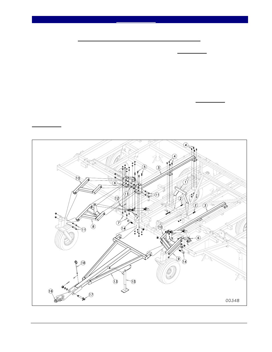
Caster Wheel Linkage & Hitch Pole Assembly
Bolt the center fold bracket (1) to the
center frame as shown in Figure 6. Use 3/4 x 2
1/2 hex bolts (2) with lock washers & hex nuts.
Bolt the center frame truss (3) to the center
frame using 5/8 x 1 1/2 hex bolts (4), lock
washers and hex nuts, and 3/4 x 2 hex bolts (5)
with lock washers and hex nuts.
U-bolt the gauge wheel arm mount (6)
to the center brace bar with three 3/4 x 3 x 5 1/2
u-bolts (7). Insert the left & right bottom center
gauge wheel arms (8 & 9) and secure with 1 x 5
1/2 special hex bolts (11) and nylon lock nuts,
do not torque.
Attach the top gauge wheel arms (10)
with the same 1 x 5 1/2 special hex bolt and
nylon lock nut, do not torque. Connect the
turnbuckle to the bottom arms with a 1 x 2 3/4
clevis pin (12), machine washer and 3/16 x 2
cotter pin. See Caster Wheel Assembly,
Section 3, Transport in parts manual, for caster
wheel exploded diagram.
Bolt the hitch pole (13) to the brace bar
with two 1 1/4 x 7 Gr. 8 hex bolts (14), secure
with 1 1/4 lock nuts but do not torque. Insert
the tongue jack (15) on the hitch pole jack tube.
Bolt the hitch clevis (16) to the hitch pole with
1 1/2 x 11 safety chain bolt (17), machine
washers, slotted hex nut and 1/4 x 3 cotter pin.
Attach hose holder (18) with 1/8 x 1 1/2 cotter
pin.
Figure 6
4/16/2008
- 6325 Series VII Field Cultivator-Floating Hitch Operator Manual 6323 Series VII Field Cultivator-Floating Hitch Operator Manual 6320 Series VII Field Cultivator-Floating Hitch Operator Manual 6318 Series VII Field Cultivator-Floating Hitch Operator Manual 6116 Series VII Field Cultivator-Floating Hitch Operator Manual 6113 Series VII Field Cultivator-Floating Hitch Operator Manual