Level bar assembly – Great Plains 6328 Series VII Field Cultivator-Floating Hitch Operator Manual User Manual
Page 20
Section 1: Assembly
Great Plains Mfg., Inc..
Series VII 6113-6328 Field Cultivator, Floating Hitch 560-204M
1/17/2005
18
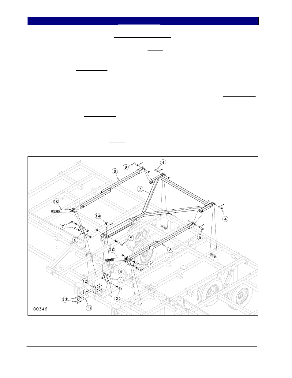
Level Bar Assembly
Slide the H-bracket (1) down over the
cylinder mount tube as shown in Figure 5. Bolt
in place with a 3/4 x 6 bolt (2) and lock nut.
Draw this nut up but do not torque, as this part
must pivot.
Connect the level bar (3) to the torque
tube using two 1 x 3 3/8 usable headed pins (4),
1” flat washers, 1” machine washers and 3/16 x
2 cotter pins. Install the 1 x 9 Gr. 8 bolt (5)
through the level bars and H-bracket. Draw up
snug with a 1” lock nut (do not torque).
Slide the leveling links (6) over the
leveling link mounting tubes as shown. Bolt in
place with 1 x 6 special thread hex bolts Gr. 8
(7), securing with nylon lock nuts. Do not
torque, as this part must pivot freely. Connect
the caster wheel level bars (8) to the level bar
(3) using two 1 x 4 1/2 usable headed pins (9),
1” machine washers and 3/16 x 2 cotter pins.
Bolt the caster wheel level bar (8) to the
turnbuckle assembly (10) through the leveling
link (6) as shown. Use the 1 x 6 special thread
hex bolt (7) and nylon lock nut. Do not torgue
as before.
Attach the rebound valve mounting
bracket (11) and valve mounting bracket plate
(12) with four 1/2 x 4 1/2 bolts (13) using lock
washers and hex nuts. Insert the 3/4 x 3
transport pin w/keeper (14) in holder.
Figure 5
4/16/2008
- 6325 Series VII Field Cultivator-Floating Hitch Operator Manual 6323 Series VII Field Cultivator-Floating Hitch Operator Manual 6320 Series VII Field Cultivator-Floating Hitch Operator Manual 6318 Series VII Field Cultivator-Floating Hitch Operator Manual 6116 Series VII Field Cultivator-Floating Hitch Operator Manual 6113 Series VII Field Cultivator-Floating Hitch Operator Manual