Section 1: assembly, Center torque tube & walking beam assembly, Section 1 assembly – Great Plains 6328 Series VII Field Cultivator-Floating Hitch Operator Manual User Manual
Page 16: Assembly
Section 1: Assembly
Great Plains Mfg., Inc..
Series VII 6113-6328 Field Cultivator, Floating Hitch 560-204M
1/17/2005
14
Assembly
This section covers the proper assembly of the implement. The reference numbers on the
figures give you an indication of the order of assembly. For a complete breakdown of any part not
shown in this assembly section, refer to the parts manual for proper location. Refer to the Appendix
for proper bolt torque values.
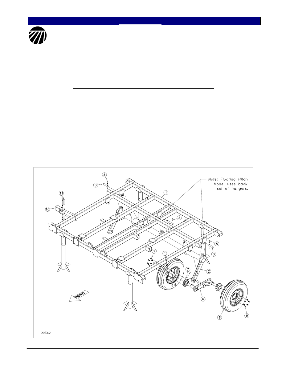
Center Torque Tube & Walking Beam Assembly
After uncrating the machine, place the
center frame (1) Figure 1, in the center of your
work area on stands. Pin the torque tube (2) to
the center frame with the 1 1/4 x 6 pins (3) and
1 1/4 x 7 pin (4), secure them with the 3/8 x 2
1/4 Gr. 8 hex bolts (5) & top lock nuts.
Slide the pivot spindle of the walking
beam assembly (6) into the sleeve at the end of
the torque tube wheel arm. It is a good idea to
put some form of anti-seize on the spindle
before you insert it. Line up the hole in the
spindle with the hole in the sleeve and secure
with 5/16 x 3 clevis pin (7) with 5/32 x 1 1/2
cotter pin.
When both walking beams have been
installed, bolt on the 9.5L x 15, 8 ply tires (8)
with the 1/2 x 1 1/4” lug bolts (9).
Bolt the 4 x 4 K-Flex Stubs (10) onto
the center frame with two 1/2 x 5 1/2 hex bolts
(11) with lock washers and hex nuts. See
Section 4 for placement dimension.
Figure 1
- 6325 Series VII Field Cultivator-Floating Hitch Operator Manual 6323 Series VII Field Cultivator-Floating Hitch Operator Manual 6320 Series VII Field Cultivator-Floating Hitch Operator Manual 6318 Series VII Field Cultivator-Floating Hitch Operator Manual 6116 Series VII Field Cultivator-Floating Hitch Operator Manual 6113 Series VII Field Cultivator-Floating Hitch Operator Manual