Great Plains PL8030 User Manual
Before you start, General information, Assembly instructions
1
Assembly Instructions
Great Plains Mfg., Inc.
© Copyright 1996 Printed 8/23/12
Used with:
•
407-068M
Pull-Type Planter
Liquid Fertilizer Option
PL6030 & PL8030 Pull-Type Planter
Before You Start
These option assembly instructions contain only information on
assembling the attachment to the main unit. A detailed Opera-
tor’s Manual was supplied with the main unit when it was pur-
chased. For more specific information on safety concerns refer to
the Operator’s Manual. Also included in the Operator’s Manual is
important information on operation, adjustment, troubleshooting,
and maintenance for this attachment (some of these sections do
not apply to all options).
A separate Parts Manual for replacement parts can be pur-
chased from your dealer. Have model and serial numbers handy
when placing an order.
Manual Part Numbers:
• Pull-Type Planter Operator’s Manual . . . . . . . . . . .401-032M
• Pull-Type Planter Parts Manual . . . . . . . . . . . . . . . 401-032P
■
When you see this symbol, the subsequent instructions
and warnings are serious - follow without exception. Your
life and the lives of others depend on it!
!!
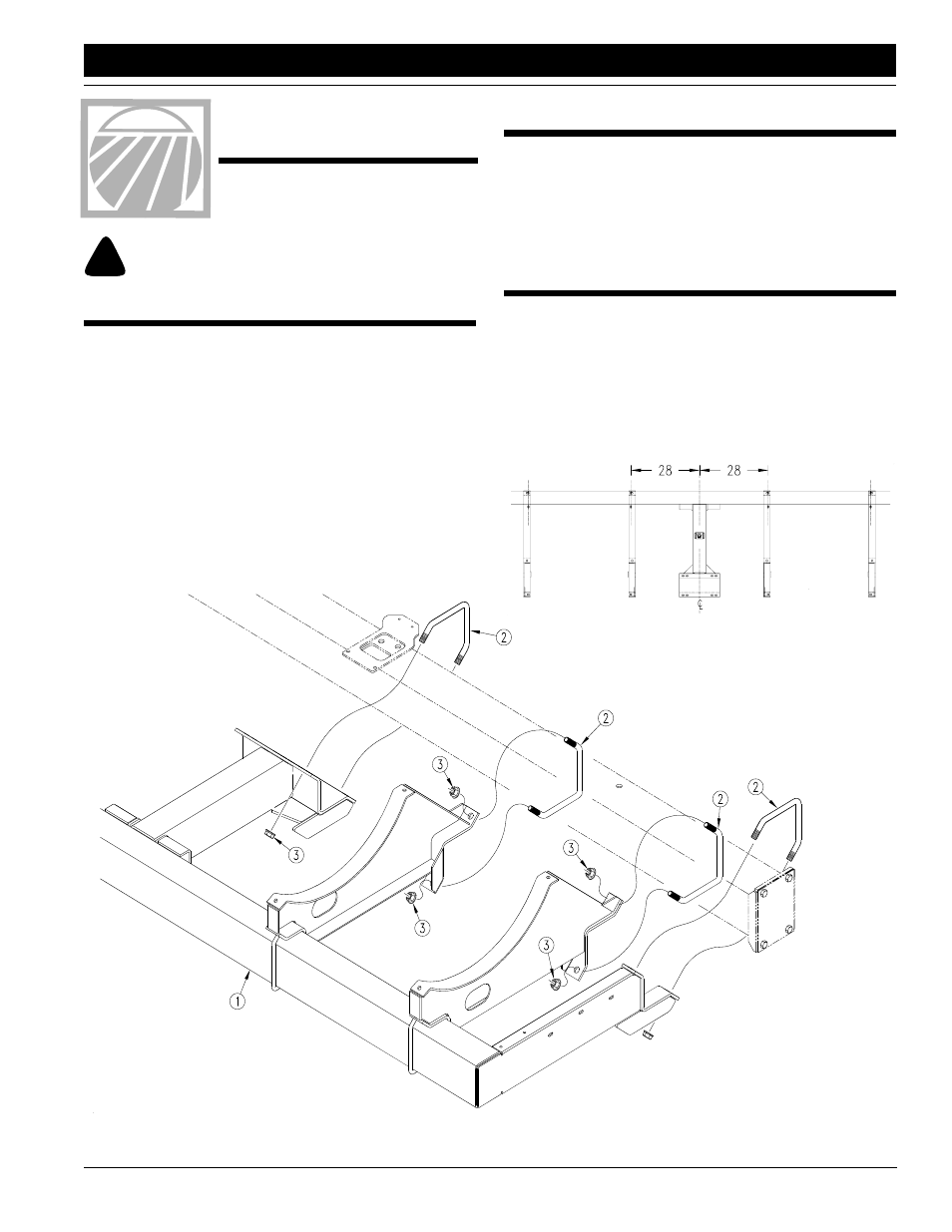
Figure 1
15744
General Information
These option assembly instructions apply to the Liquid Fertilizer
Options listed below:
407-017A
Liquid Fertilizer 6-30 Vantage I
407-018A
Liquid Fertilizer 8-30 Vantage I
Starting on page 6 is a detailed listing of parts included in these
kits. Use this list as a checklist to inventory parts received.
Assembly Instructions
For PL6030 & PL8030 follow steps 2, 3 & 8. If attaching the Liq-
uid Fertilizer Option to a PT6030 or PT8030 follow all steps.
Refer to Figure 1:
1.
Attach the fertilizer bar assembly (#1) to planter frame using
3/4" corner u-bolts (#2) and 3/4" hex flange nuts (#3). Use
the dimensions shown in Figure 2 as reference points to at-
tach the inside tank supports. The outside tank support
should be located at the proper distance for the tank de-
pending on whether the planter is a 6 row or 8 row.
15748
Figure 2
Document Outline
- 407-017A Liquid Fertilizer 6-30 Vantage I
- 407-018A Liquid Fertilizer 8-30 Vantage I
- 15745
- 15746
- Figure 4
- Figure 5
- Figure 6
- Figure 1
- Before You Start
- General Information
- Assembly Instructions
- 15748
- 2. Place saddle (#4) on tank supports and attach with 1/2" x 1 1/4" long hex bolts (#5) and 1/2" hex flange nuts (#6). Be sure the chemical warning decal (#7) is attached to saddle.
- 3. Hold tank (#8) in place by fastening tank shield weldment (#9) to saddle with 3/8" x 2 1/2" long hex bolts (#10), 3/8" x 3/4" long hex bolts (#11) and 3/8" hex flange lock nuts (#12).
- 4. Attach right hand pump mount (#13) and left hand pump mount (#14) to mounts (#15) using 3/8" x 2 3/4" long hex bolts (#16) an...
- 5. Mount the squeeze pump assembly (#20) to pump mounts with 3/8" x 1" long hex bolts (#21), 3/8" flat washers (#22) and 3/8" hex nuts (#23). Attach fertilizer case (#24) to the right hand pump mount.
- 6. Attach fertilizer cover (#25) to fertilizer case with knob (#26).
- 7. For 8-row planters attach counter shaft (#28) using couplers (#27) & (#29).
- 8. Assemble plumbing as shown in Figure 6 with the parts listings on page 4. Be sure to use Rectorseal (#12) on all fittings. Cut to length 3/8" diameter hose to fit your coulter option.