Unfolding, Remove transport locks – Great Plains DVN8324 Operator Manual User Manual
Page 30
26
8315-8324DVN
Great Plains Manufacturing, Inc.
550-466M
11/25/2013
Fold: Close Locking Valves (page 26)
Cutting Hazard - Sweeps are sharp:
Be careful of sweeps while installing locking pins. Sweeps’
points and wings are sharp. Injury could occur if near a sweep.
Ensure the lock valve
is in the closed position (90
degrees from hose) as shown. Place locking pins
in the transport position.
Unfolding
These steps presume a implement raised and folded for
transport, such as at initial delivery. Follow the detailed
instructions in step 7 through step 16, beginning on this
page, until this is a familiar operation.
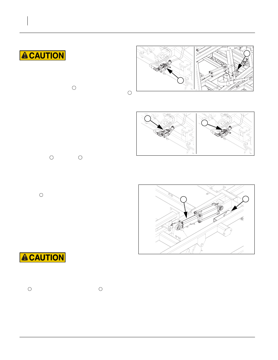
Refer to Figure 17
Locking valve is on the front of the center brace bar to pre-
vent wing movement during transport and maintenance.
Note the open
and closed
position of the valves.
7.
Move the implement to level ground with adequate
overhead and lateral clearances for the fold operation.
Remove Transport Locks
Refer to Figure 18
8.
Extend lift circuit to lift implement off the transport
locks
.
9.
Park tractor and implement. Ensure the tractor hydrau-
lics are depressurized and in the locked or closed (not
float) setting position,
10. Shut down tractor and remove the key.
11. Check that lock valve is in the locked position. Check
that the wing lock pins are in the transport posi-
tion.Inspect fold/lift cylinders, linkages, and hoses for
wear. If parts are worn, the operator should have a
qualified technician replace worn parts.
Cutting Hazard - Sweeps are sharp:
Be careful of sweeps while installing locking pins. Sweeps’
points and wings are sharp. Injury could occur if near a sweep.
12. If parts are in good working order, move transport lock
to the field position on the frame
.
13. Place locking pins in the field position.
14. Move locking valve lever to the open position slowly on
front of center bar.
15. Ensure all personal, e.g., children are out of the dan-
ger zones.
Figure 16
Wing Lock Valve (Closed) & Locking
Pins
42188
1
2
1
2
Figure 17
Wing Lock Valve (Open & Closed)
42187
42188
2
1
1
2
Figure 18
Transport Locks
42185
6
5
1
1
2