Mark for sensor hole, Mark for sensor mount holes, Drill holes for sensor mount – Great Plains PD8070 User Manual
Page 3
Great Plains Mfg., Inc.
Installation Instructions
3
02/02/2007
402-231M
Mark for Sensor Hole
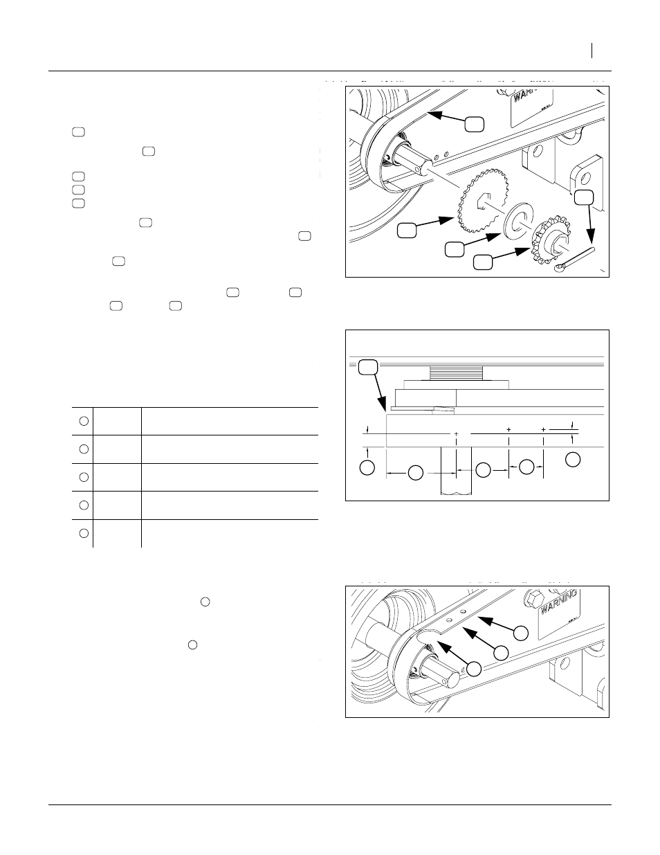
Refer to Figure 5 and Figure 6
8.
Select one new:
9.
Place the disc
on the shaft, and temporarily re-
install:
PIN COTTER 1/4 X 2 PLT
SPKT 40C15 X 7/8 HEX BORE
WASHER FLAT SAE 1
10. Slide the disc
determine the average position. Mark the shield
directly above the average top center position of
the disc
. Compare the result to the predicted
measurements in the table at step 12.
11. Remove and save the cotter pin
, sprocket
washer
and disc
Mark for Sensor Mount Holes
12. Mark for two additional holes forward and slightly to
the left of the sensor hole, as depicted in Figure 6.
Drill Holes for Sensor Mount
13. Drill or cut the sensor hole
to a diameter
between 32mm and 35mm. File off any sharp
edges.
14. Drill the mounting holes
to diameters between
6.7mm and 7.1mm.
Hole Placement
9.5mm
0.375in
Sensor hole to edge of shield
(approximate)
51mm
2.0in
Sensor hole to end of shield
(approximate)
38.1mm
1.5in
Sensor hole to rear mount hole
25.4mm
1.0in
Mount hole to mount hole
3.2mm
0.125in
Sensor/Mount centerline offset
Figure 5
Mark Sensor Hole
26003
+
Figure 6
Mark Sensor Mount Holes
26001
2
3
4
5
1
Figure 7
Cut Holes
26004
1
2