Great Plains NTA 2000 export model Assembly Instructions User Manual
Page 7
5/9/2007
148-679M
Great Plains Mfg., Inc.
7
Installation Instructions
Refer to Figure 13
32. Set the calibration trays in place using the
mounting slots in the hose support bracket.
Secure them with the new calibration tray
clips (a) and the plastic knob (b) removed in
step 21 on page 5.
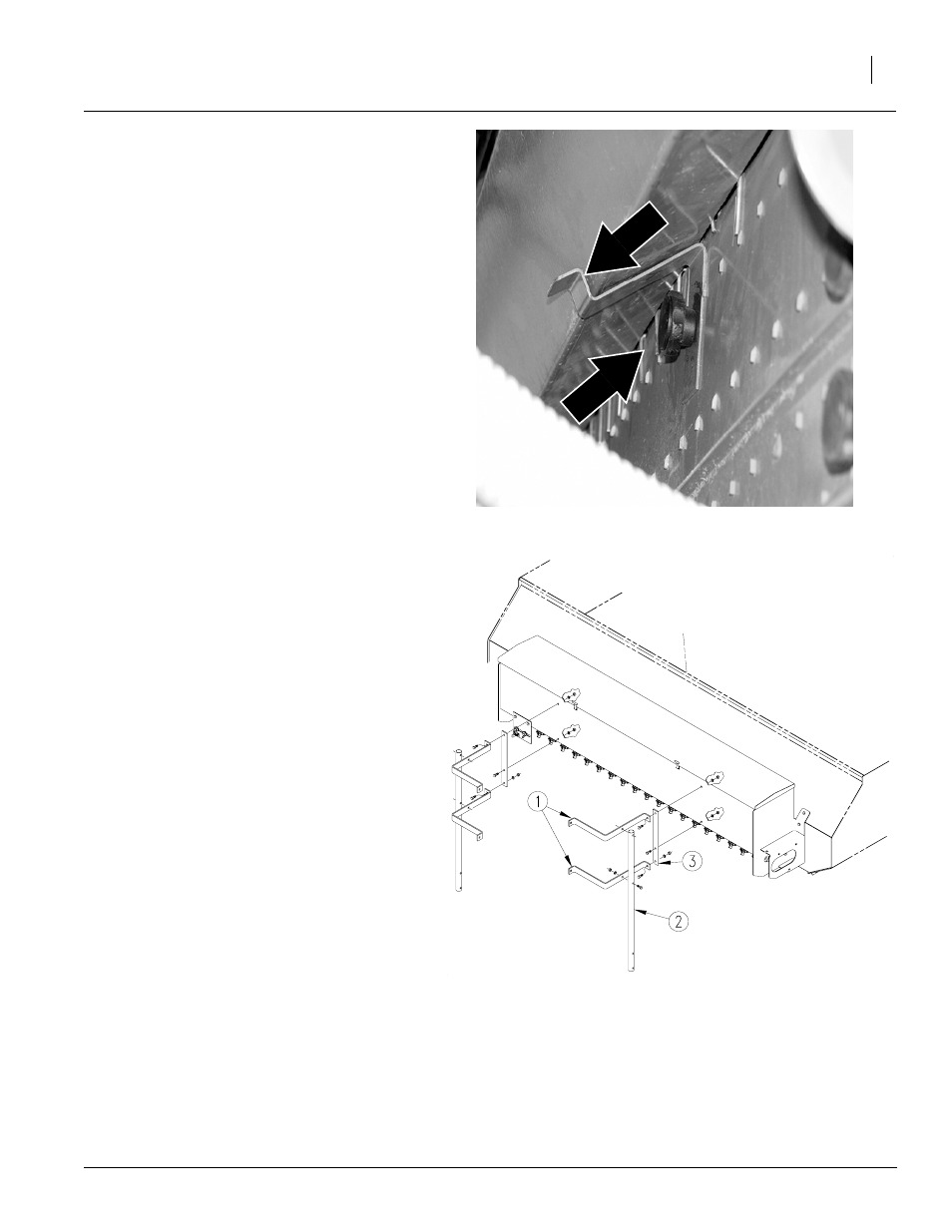
Refer to Figure 14
33. Mount handrail post (2) to the upper platform
using 3/8" x 2" bolts, 3/8" lock washers and
3/8" nuts removed earlier. Tighten bolts.
34. Mount handrails (1) to the handrail posts (2)
using 3/8" x 1 3/4" bolts, 3/8" lock washers
and 3/8" nuts removed earlier. Leave bolts
loose.
35. Align the middle hole of the handrail ties (3)
with the bottom mounting holes of the small
seeds box. Hold handrail ties in place with
3/8" x 1" bolts, 3/8" lock washers and 3/8"
nuts. Leave bolts loose.
36. Align the top hole in the handrail ties (3) with
the top holes in the small seeds box. Align the
top handrails (1) with the holes and secure
with 3/8" x 1" bolts, 3/8" lock washers and 3/8"
nuts. Leave bolts loose.
37. Align the bottom handrails (1) with the holes
at the bottom of the handrail ties (3) and se-
cure with 3/8" x 1" bolts, 3/8" lock washers
and 3/8" nuts.
38. Bolt upper and lower handrails (1) to the step
handrail with 3/8" x 1 3/4" bolts, 3/8" lock
washers and 3/8" nuts removed earlier. Tight-
en all bolts.
Figure 13
Calibration Tray Clip
a
20208
b
Figure 14
Handrail Assembly
20206