Great Plains NTA 2000 export model Assembly Instructions User Manual
Page 3
5/9/2007
148-679M
Great Plains Mfg., Inc.
3
Installation Instructions
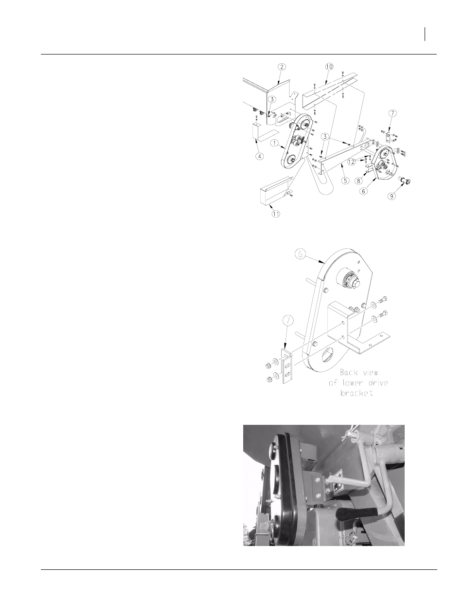
Refer to Figure 3
7.
Remove the plastic guard from the cup drive
assembly (1) and mount the cup drive assem-
bly (1) to the right-hand side of the small seeds
box (2). Align the sprockets with the two shafts.
Secure drive (1) in place with three 3/8 x 3/4"
bolts and 3/8" flange lock nuts. Tighten bolts
and replace plastic guard.
8.
Slide a 5/16" nut clip (3) over the hole in the
bracket above the sprockets in drive assembly
(1). Attach the chain guard (4) to the bracket
using a 5/16" x 3/4" bolt and 5/16" lock washer
and tighten bolt.
9.
Remove the roll pin from the end of the calibra-
tion crank shaft. Keep roll pin for later use.
10. Align the hole in the drive assembly (9) with the
hole in the calibration crank shaft. Position the
set screw in the drive assembly with the flat
area on the shaft and reinstall the roll pin re-
moved in step 9 and tighten set screw against
shaft.
Refer to Figure 4
11. Remove plastic guard from lower drive bracket
(6). Attach the drive angle bracket (7) using the
smaller set of holes to the back side of the low-
er drive bracket (6). Use two 3/8" x 1" bolts, four
3/8" flat washers and two 3/8" nuts. Snug bolts
and nuts leaving them loose enough to allow
the bracket to slide.
Refer to Figure 5
Note: Figure five shows the lower drive assembly in
the mounted position.
Refer back to Figure 3
12. Remove the two M8 metric bolts located in the
top of the variator gearbox mount. Place spac-
er (8) over holes in the top of the variator gear-
box mount and place the lower drive bracket (6)
on top of spacer (8). Align sprocket of the lower
drive bracket (6) with the sprocket of the drive
assembly (9). Secure lower drive bracket with
two M8 x 1.25 x 25 metric bolts (12) and tighten
bolts.
13. Slide the drive angle bracket (7) towards the
drill until it makes contact. Make sure the
sprockets are aligned and mark the position of
the two larger holes. Remove the two metric
bolts and remove the lower drive bracket (6).
14. Drill two 17/32" holes at the marks made in the
previous step.
Figure 3
Drive Assembly
20204
Figure 4
Lower Drive Assembly (back view)
20214
Figure 5
Lower Drive Assembly (mounted)
21764