Ab c d – Great Plains NTA 2000 export model Assembly Instructions User Manual
Page 5
5/9/2007
148-679M
Great Plains Mfg., Inc.
5
Installation Instructions
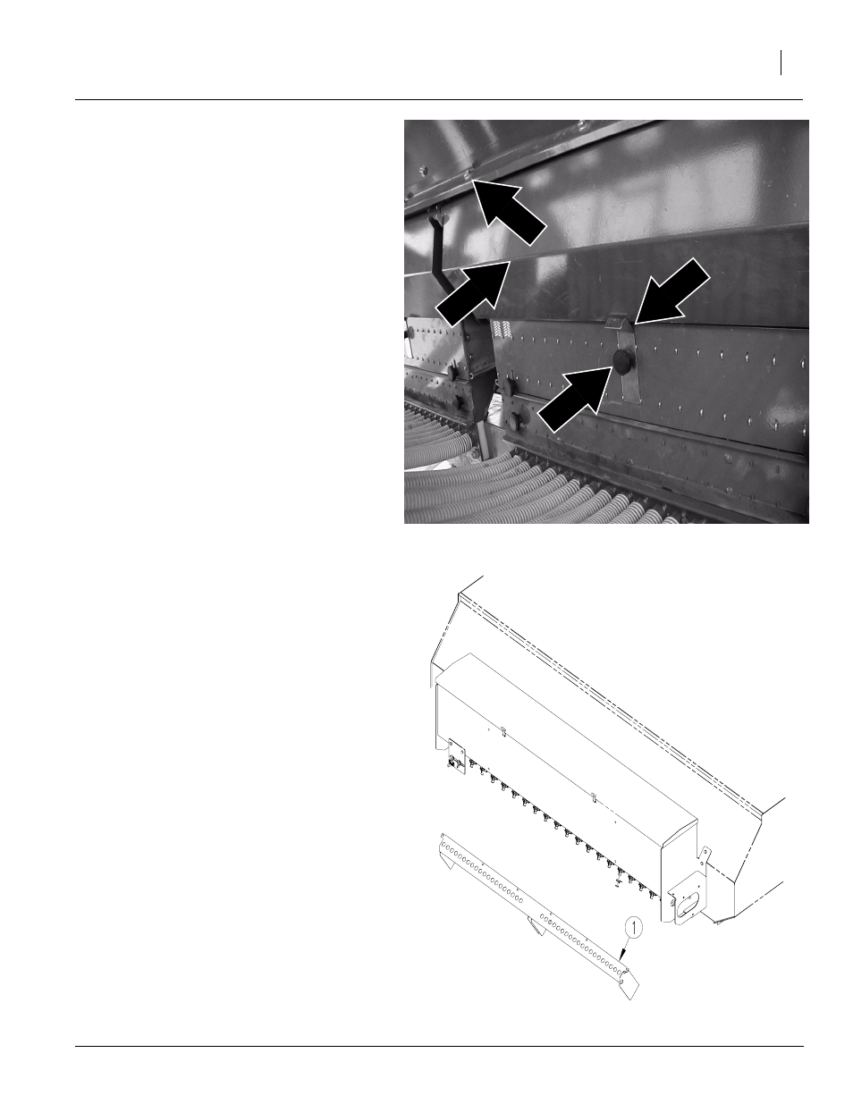
Refer to Figure 8
21. On the right-hand side of the drill undo the
plastic knob (a) and remove the calibration
clip (b) and discard clip. Remove calibration
tray (c). Keep calibration tray and plastic
knob. Repeat process for the left-hand cali-
bration tray.
22. After the trays are removed, loosen bolts (d)
from box.
Note: It will be necessary to remove two bolts from
box. Refer to hose support bracket to determine
which bolts to remove. Keep bolts to reinstall later.
Refer to Figure 9
23. Attach hose support bracket (1) to the main
drill box using the bolts which were loosened
or removed in step 22.
a
b
c
d
Figure 8
Calibration Trays
19924
Figure 9
Drive Assembly
20205
This manual is related to the following products: