Update clutch shaft, Install small seeds clutch sprocket – Great Plains 1005NT Assembly Instructions User Manual
Page 8
6
7ft and 10ft EWNT Small Seeds
Great Plains Manufacturing, Inc.
123-535M
06/02/2008
Update Clutch Shaft
The existing clutch shaft is updated with a third sprocket
for Small Seeds. The clutch shaft is located at the front of
the main seed box, below the gearbox or transmission.
If you have a late model drill, you may already have a
Small Seeds drive sprocket installed.
Inspect the existing clutch shaft
.
If it has a
3
⁄
16
in diameter hole
about 22in from the
right end of the shaft, continue at step 9.
If the shaft already has an unused 15T sprocket
mounted at this location, continue at “Seed Box
Mounting” on page 7.
If you have a very early model drill, it may not have
the pin hole for the sprocket. Have your dealer con-
tact the factory regarding a replacement shaft.
9.
Carefully note the location of all existing bearings,
sprockets, spacers and gears.
Note: In addition to the detail in Figure 12 on page 12,
digital or instant photography may prove useful
during reassembly. It is suggested lines be scribed
on the shaft to mark the exact location of each
removed or loosened part.
10. Remove only enough existing parts to allow placing
a new sprocket and retainers on that portion of the
shaft.
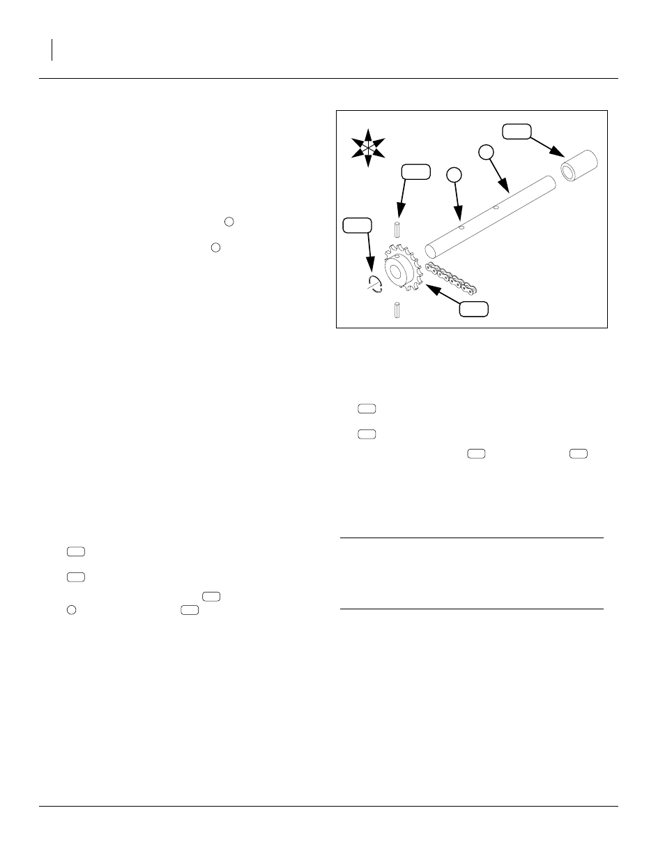
Install Small Seeds Clutch Sprocket
11. Select one new:
808-098C SPKT 40 B 15 X 1 BORE
and two new:
805-080C PIN ROLL 1/8 X 1LG. PLT.
12. Install the 15 tooth sprocket
with the two roll pins
Note: One roll pin may be left out for lighter shear.
13. Depending on your drill model, select one of:
or two of:
14. Install either snap ring
needed to retain the sprocket if the roll pins shear. A
retainer is not required on drills where the shear
sprocket is naturally trapped by other parts on the
clutch shaft.
15. Install the new shaft on the drill.
IMPORTANT !
When placing the 15 tooth sprocket AND any retain-
ing hardware on the shaft, carefully follow the assem-
bly illustration corresponding to the width of your drill.
Refer to Figure 12 on page 12.
Figure 4
Remove Existing Clutch Shaft
10926
U
D
L
R
B
F
1
2
- 1005NG Assembly Instructions 1005NF Assembly Instructions EWNT10 Assembly Instructions EWNG10 Assembly Instructions EWNF10 Assembly Instructions EWNT7 Assembly Instructions EWNG7 Assembly Instructions EWNF7 Assembly Instructions 705NT Assembly Instructions 705NG Assembly Instructions 705NF Assembly Instructions