Assembly, S3t bar & spike drag – Great Plains S3T User Manual
Page 4
550-487M
12/22/2011
4
S3T & Reel
Great Plains Manufacturing, Inc.
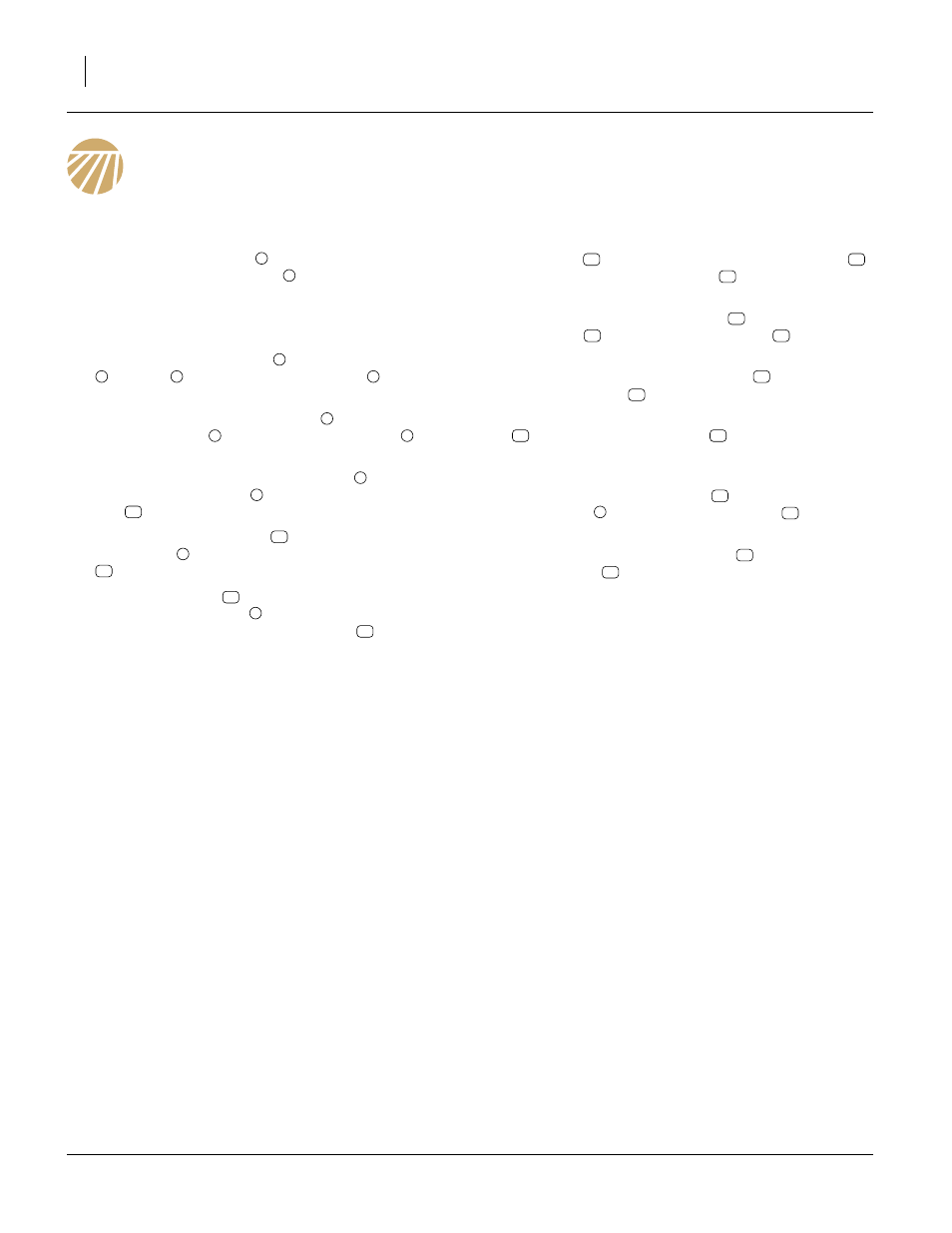
Assembly
S3T Bar & Spike Drag
Refer to Figure 2
1.
Attach arm assemblies
to rear bar of machine with
3/4 x 4 1/32 x 4 1/2 u-bolts
, 3/4 lock washers and
nuts.
Note: See Layout drawings pages 8-16 for proper arm
placements.
2.
Mount front bar assembly
to rear of adjustable link
and link
, with 5/8 x 3 1/2 hex bolts
, 5/8 top
lock nuts.
3.
Attach top of 15 link drag chains
to bottom side of
arm assemblies
with 3/8 x 1 1/4 hex bolts
3/8
lock washers and 3/8 nuts.
4.
Slide lower link of 15 link drag chains
into slot on
spike drag bar bracket
, secure with 3/8 x 2 1/2 hex
bolt
, and top lock nut.
5.
Align holes in harrow link
with holes in spike drag
bar bracket
, secure with 5/8 x 2 7/8 special bolts
and 5/8 top lock nuts.
6.
Attach two plates
(one on top and one on bot-
tom) of arm assembly
. Note measurement of 5 5/
16” from rear of spring to front of plate
. Attach key
hole plate
to outside of plates key hole plates
.
Secure with 5/8 x 6 hex botlts
, 5/8 lock washers
and 5/8 nuts.
7.
Attach safety chain spring loop
to inside of key
hole plate
with 1/2 x 1 1/2 hex bolt
, 1/2 flat
washer, 1/2 lock washer and 1/2 nut.
8.
Attach one end of 25 link pull chain
to slotted hole
in key hole plate
.
9.
Attach other end of chain to front drag link assembly
with 7/16 x 1 1/2 hex bolt
, 7/16 flat washers
(one on bolt and one under plate) and 7/16 nylock
nut.
10. Attach polyurethane bumper
to top side of arm
assemblies
with 5/16 x 1/2 hex bolts
and 5/16
flat washers.
11. Attach front bar mount assembly
with 1/2 x 2 1/2 x
3 1/2 u-bolts
, 1/2 lock washers and 1/2 nuts.
12. All bolts may be tightened to specs, See “Torque
1
2
3
4
5
6
7
1
8
7
9
10
11
9
12
13
1
13
14
13
15
16
14
17
18
14
19
20
21
1
22
23
24