Liquid fertilizer rate, Setting liquid fertilizer rate – Great Plains YP2425F-2470 Material Rate User Manual
Page 39
2013-09-23
401-406B
Great Plains Manufacturing, Inc.
37
Liquid Fertilizer Rate
Setting Liquid Fertilizer Rate
Note: YP2425F dry fertilizer rate charts are found in
Supplement manual 403-362M.
If your planter is equipped with one or both optional
fertilizer manifold systems, it does not include the tank.
If the planter has a Type 2
a
(formerly referred to as a
“starter”) manifold, it may rely on an off-planter pump, or
may use one or two ground drive pumps on the planter.
For example, a Great Plains SML cart would use a
ground drive pump on the planter.
See “Ground Drive Fertilizer Rate” on page 40 for
ground drive pump configuration.
If the planter has a Type 3
(formerly referred to as a
“hi rate”) manifold, it relies on an off-planter pump,
typically the pump on a Great Plains PFC1600 or
PFC2000 tank cart.
Rate setting for a PFC cart pump is found in the cart’s
Operator manual.
Rate is controlled by the pump. Consistent distribution
requires using the correct size orifices in the manifolds. If
the orifice size is too large, flow may not be even across
all rows. If the orifice size is too small, material may be
dumped at the relief valve.
See “Liquid Fertilizer Rate” on page 37 for orifice
information.
The YP2425 planter optionally includes one or two
fertilizer manifolds, and may include one or two
ground-driven pumps for the Type 2 manifold. Tank(s)
and any off-planter pump(s) are usually located on a
trailing tank cart.
The Great Plains PFC1600 (single tank) and PFC2000
(dual tank) tanks include a single pump. Refer to the tank
Operator’s Manual for pump settings at the tank.
Fertilizer rate is independent of seed rate. Fertilizer rates
are set by the pump systems. On-planter ground drive
pump operations are described on page 40 and in the
YP2425 Operator’s Manual. Off-planter pump operations
are described in the tank manual.
Manifold systems include orifice plates at each row unit
drop line. Each fertilizer system normally includes a
pressure relief valve and strainer. These components
affect consistency of flow across all rows.
Adjust the relief valve(s) per the YP2425 Operator
Manual and/or tank Operator Manual.
a. Type 2 and Type 3 are described in the YP2425 Operator manual, under Setup topic “Fertilizer Connections”.
34128
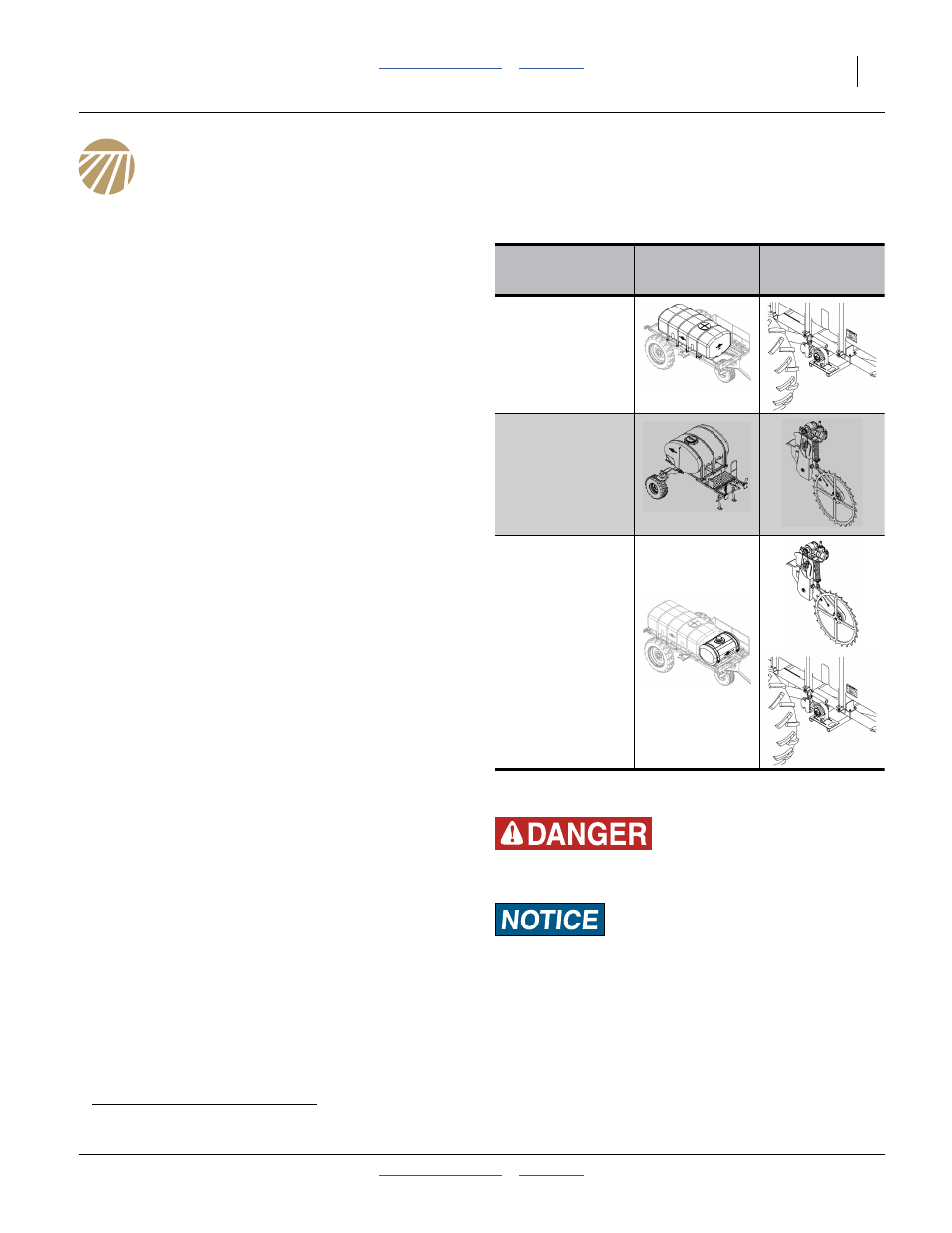
Installed
Manifold(s)
Source
(Tank)
Pump
Type 3
Type 2
Type 2
and
Type 3
Possible Chemical Hazard:
Wear protective gloves when changing orifice plates.
Material Loss/Equipment Damage Risk:
Set application rate at pump using pump drive chart., not by
orifice size. Orifice size is only used to create 15-65 PSI back
pressure to provide even flow between rows. An orifice size
too small causes material loss at relief valve. A size too large
can cause application imbalance across the planter.