Detracker assembly (optional), Detracker placement – Great Plains 4000TT Predelivery Manual User Manual
Page 24
20
1200-4000TT
Great Plains Manufacturing, Inc.
586-201Q
02/11/2014
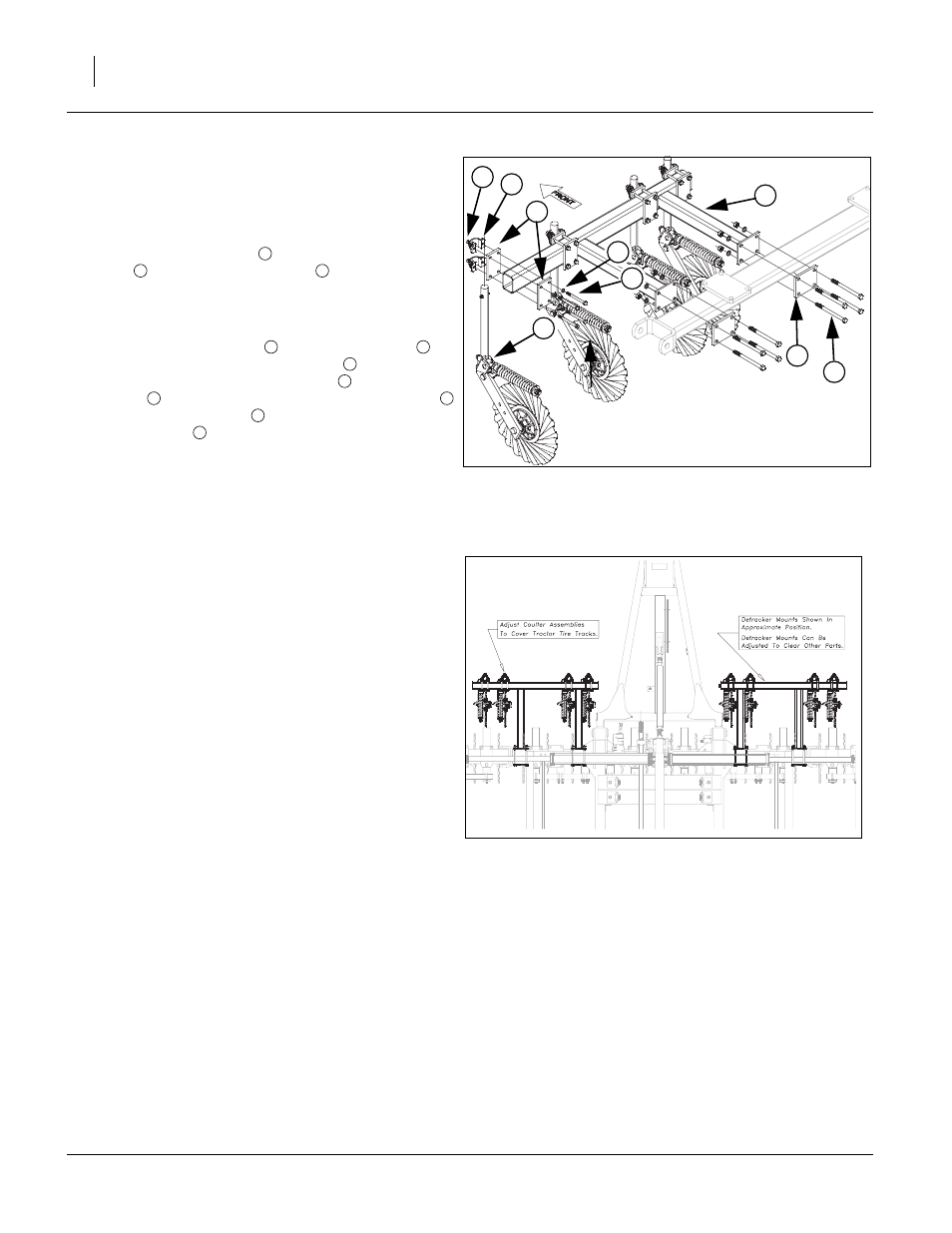
Detracker Assembly (Optional)
Note: See detracker assembly in “Parts Manual” for com-
plete parts breakdown.
Refer to Figure 17
69. Attach detracker mount
to center gang hanger with
plate
, using 5/8 x 8 hex bolts
, 5/8 lock washers
and 5/8 nuts. See “Detracker Placement” on
page 20, for proper placement. Repeat same proce-
dure for other side.
70. Mount shank assembly
to detracker mount
by
aligning the holes in the two plates
(one on each
side). Align holes in shank clamps
on front side of
shank
, secure assembly with 1/2 x 5 hex bolts
and 1/2 lock washers
. These bolts thread into
shank clamp
. See “Detracker Placement” on
page 20, for proper placement and adjustment.
71. Once every thing is adjusted, all bolts may be tight-
ened to specs, See “Torque Values Chart” on
page 23.
Detracker Placement
Refer to Figure 18
72. Adjust detracker frames to approximate location as
shown in Figure 5 to clear other parts on machine.
Adjust coulter assemblies to cover tire tracks.
Note: See detracker height adjustment in “Operator Man-
ual” for detracker adjustments before going to field.
Figure 17
Detracker
42829
8
4
6
9
3
2
5
7
1
1
2
3
4
1
5
6
4
7
8
6
Figure 18
Detracker Placement
41630