Assembly, Hitch assembly, Wing assembly – Great Plains 4000TT Predelivery Manual User Manual
Page 12: Hitch assembly wing assembly
586-201Q
02/11/2014
8
1200-4000TT
Great Plains Manufacturing, Inc.
Assembly
Hitch Assembly
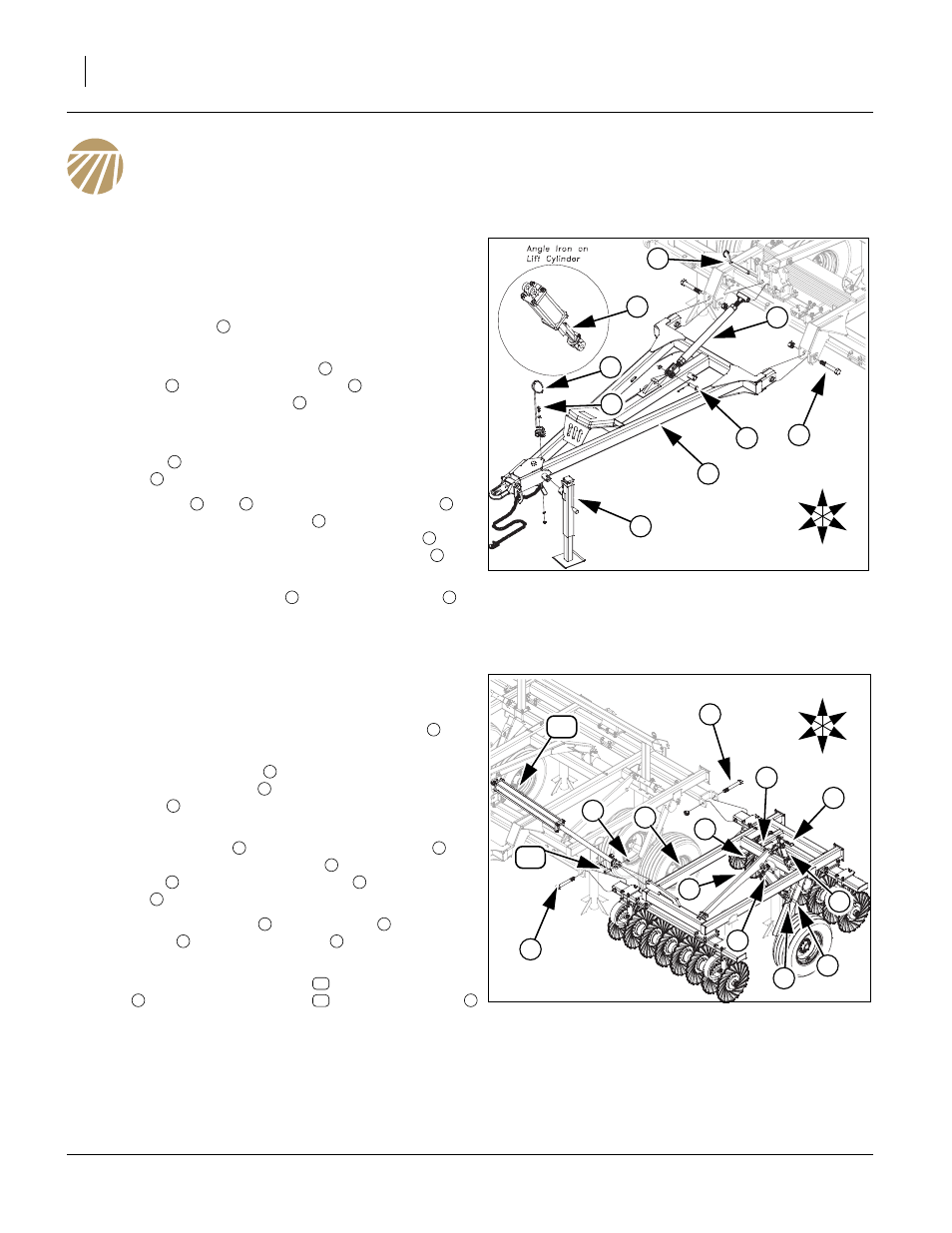
Refer to Figure 4
Note: The center will be shipped pre-assembled.See “Parts
Manual for part numbers and description of parts.Place
center frame on stands if available, if not, place turbo
gangs on floor and for ease of attaching wing frames
put a cut angle
in center lift cylinders to raise gangs
off floor.
18. Remove the 1 1/4 x 8 Gr. 8 bolts
from the rear of hitch
assembly
. Bolt he hitch assembly
to center frame
with the 1 1/4 x 8 Gr. 8 bolts
and 1 1/4 top lock nuts.
Tighten bolts snug, do not torque, as the hitch must pivot
freely.
19. Instal jack
on front outside of hitch to support the front
of hitch
.
20. Remove pins
and
from turnbuckle assembly
.
Install the turnbuckle assembly
between the level bar
rocker and hitch frame ear with the 1 x 9 1/2 pin
, 3/8 x
1 3/4 quick pin (rear) and the 1 x 3 3/8 clevis pin
,
machine washer and 3/16 x 2 cotter pin (front).
21. Bolt the spring hose holder
with 1/2 x 1 1/2 bolt
, 1/
2 flat washer, 1/2 lock washer and 1/2 nut.
Wing Assembly
Refer to Figure 5
Note: The wings will come pre-assembled. Models 1800 and
2400 will be shipped with wings attached. On models
3000 and 4000, place wing frame assemblies
on
stands next to center frame.
22. Remove 1 1/4 x 10 bolts
from center frame hinge. Bolt
wing frame assemblies
to center frame with the 1 1/4
x 10 bolts
1 1/4 top lock nuts. Tighten bolts snug, do
not torque, as the wing must pivot freely.
23. Remove 1 x 3 bolts
from turnbuckle assembly
.
Align holes in cylinder mount bar
and turnbuckle
assembly
, re-install the 1 x 3 bolts
, 1 machine
washer
and 1 lock nut.
24. Attach wing lift cylinder
to torque tube
with 1 x 3 1/
8 pin clevis
, 1 machine washer
and 3/16 x 2 cotter
pin.
25. Attach rod end of fold cylinders
to wing frame assem-
blies
with 1 x 3 1/8 clevis pin
1 machine washer
and 3/16 x 2 cotter pin.
26. Do not hook up rod end of fold cylinder until system is
purged of air. See “Purging Hydraulic System” on
page 15.
27. Bolt may be tightened to specs, See “Torque Values
Figure 4
Hitch
42072
9
U
D
F
B
L
R
8
7
2
5
4
3
6
1
1
2
3
3
2
4
3
5
6
7
7
5
6
8
9
Figure 5
Wing
42073
U
D
F
B
L
R
2
2
8
9
7
5
1
6
3
4
6
10
11
6
1
2
1
2
3
4
5
4
3
6
7
9
8
6
10
1
11
6