Relief valve installation, Supersweep assembly, Flighting kit – Wheatheart Hydrostatic Portable and Truck-Mount Super Sweep User Manual
Page 20: Warning
3. A
SSEMBLY
W
HEATHEART
- H
YDROSTATIC
B
IN
S
WEEP
3.3. S
UPERSWEEP
A
SSEMBLY
S
TANDARD
, P
ORTABLE
, T
RUCK
M
OUNT
, & S
UPER
S
WEEP
20
IM1 R3
3.2.4. R
ELIEF
V
ALVE
I
NSTALLATION
1. The port labelled “P” on the relief valve must be connected to the “OUT”
(pressure) side of the pump (Figure 3.6), or directly to the pressure source if
using a remote hydraulic source.
2. The port labelled “T” on the relief valve must be connected to the tank or
reservoir of the bin sweep.
3. The 2 fittings opposite “P” and “T” on the relief valve are connected to the
hydraulic motor (Figure 3.6).
4. If the motor turns the wrong way, first verify that the pressure and tank
connections are correct. If the motor still turns the wrong way, cross the
hydraulic lines between valve and motor.
3.3. SUPERSWEEP ASSEMBLY
3.3.1. F
LIGHTING
K
IT
The Supersweep flighting kit (see Figure 3.12) consists of:
• a motor coupler
• a universal section with a u-joint and floating wheel
• a straight section with a walking shoe
• two plain, straight sections
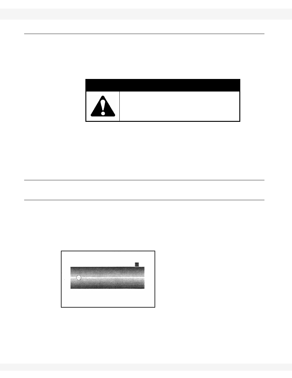
Figure 3.11 Motor Coupler for Supersweep
Note:
The motor coupler for the Supersweep (Figure 3.11) is different than the regular
bin sweep coupler.
WARNING
Be sure relief valve hook up is correct;
otherwise, the relief valve will not kick out and
serious injury or death to the operator can
occur.